
Flare Gas Recovery
Efficient Recovery and Reuse of Flare Gas with Engineered Flare Gas Recovery Systems.
.svg)
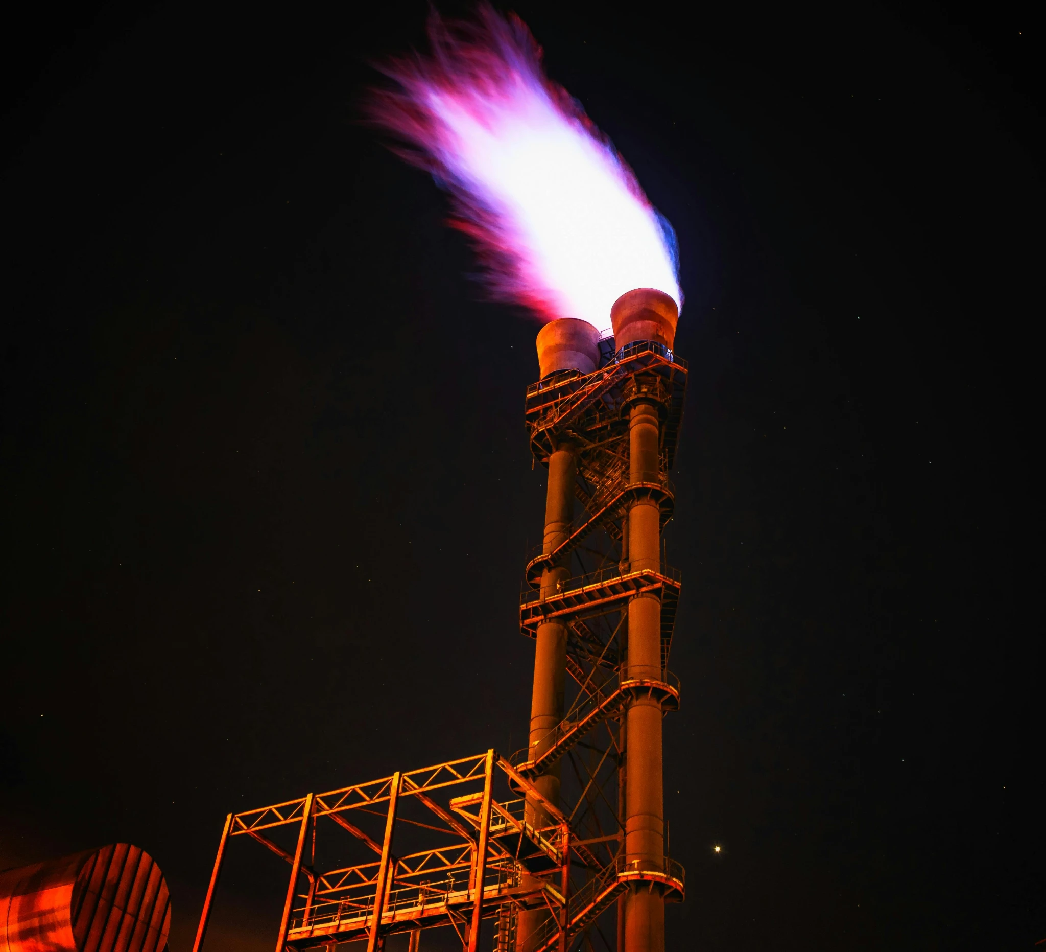
Captures routine flare gas and returns it to fuel or process, without restricting relief
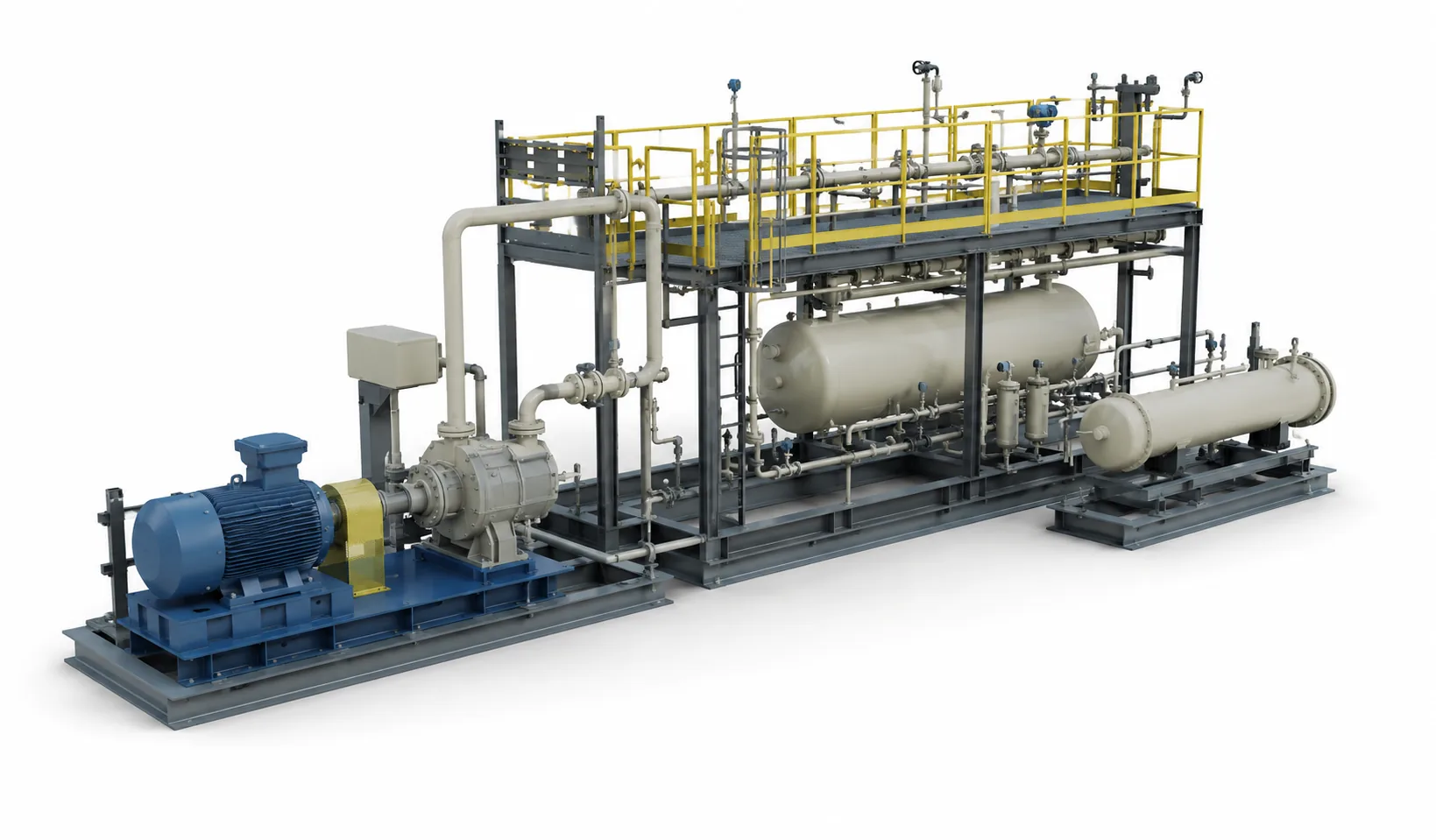
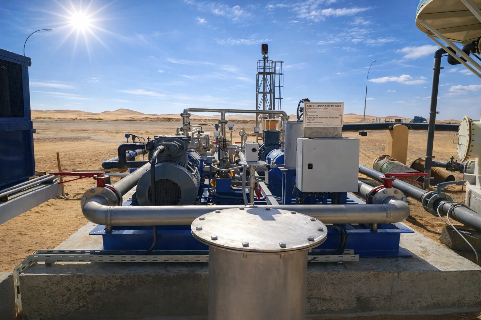
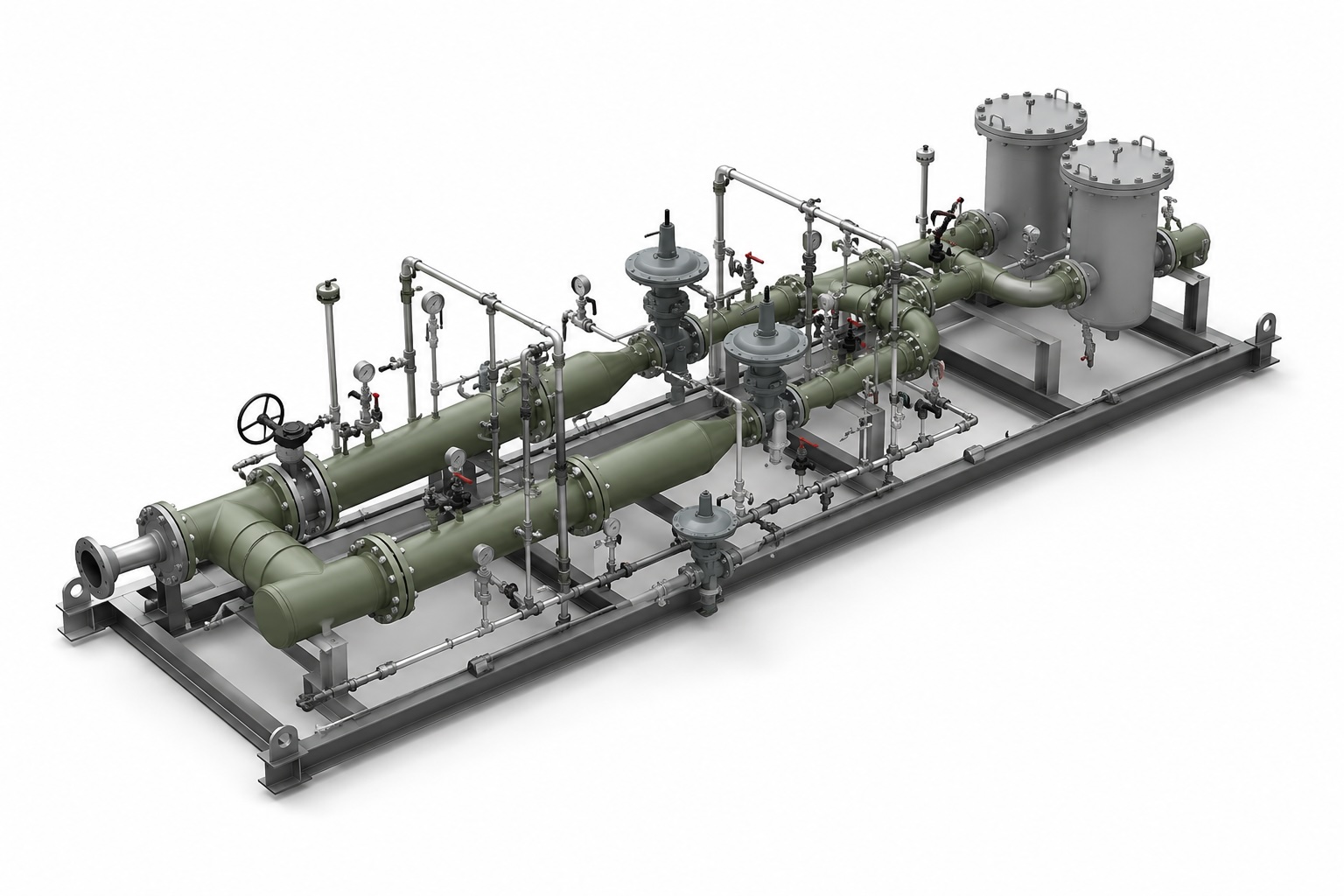
Our Flare Gas Recovery Systems (FGRS) capture excess hydrocarbon gas that would otherwise be flared and return it to the plant fuel gas system or process. By recovering routine flare gas, an FGRS reduces emissions, recovers a valuable fuel stream, and gives operators tighter control of flare header pressure, while keeping the flare immediately available for genuine upset and emergency events. Recovery runs in parallel with the flare and never restricts relief. CRA offers two recovery technologies and applies the one that fits the duty. Compressor-based recovery uses liquid ring or screw compressors and suits higher, sustained flows. Eductor-based recovery uses high-pressure gas as the motive fluid, passed through a venturi to entrain low-pressure flare gas, with no rotating gas-handling equipment. The motive gas and the recovered flare gas combine and route to fuel or process together, so this route suits sites with an available high-pressure gas source and a low-maintenance operating philosophy. Where it improves the result, both technologies can be staged together. Each FGRS is delivered as a fully integrated, skid-mounted package, engineered using CRA's experience in gas handling, compression, and combustion systems. Systems are sized for the routine flare gas profile rather than the peak relief case, and integrate into existing flare headers through a tie-in upstream of the water seal, which keeps the flare and its header unchanged.
Recovery Method
Compressor or eductor
Flare Availability
Unrestricted
Sizing Basis
Routine flow profile
Integration
Existing flare header
What is a Flare Gas Recovery?
A flare gas recovery system (FGRS) captures excess hydrocarbon gas that would otherwise be flared and routes it back to the plant fuel gas system or process, reducing routine flaring while keeping the flare immediately available for genuine upset and emergency relief.
How it works
Routine flare gas is drawn off upstream of the water seal and routed through one of two recovery paths, compressor-based or eductor-based, before it returns to fuel or process.
The system ties into the existing flare header upstream of the water seal, drawing off routine flare gas without altering the flare's relief capacity.
Liquid ring or screw compressors raise the pressure of the recovered gas, suited to higher, sustained flow volumes.
A high-pressure motive gas passes through a venturi to entrain low-pressure flare gas, with no rotating gas-handling equipment involved.
Recovered gas, whether from the compressor path, the eductor path, or both staged together, routes back into the plant fuel gas system or process.
Key Benefits
Captures and recovers excess flare gas, significantly reducing routine and non-routine flaring.
Recovered gas can be reused as fuel or process gas, improving overall plant efficiency.
Maintains controlled flare header pressure under fluctuating operating conditions.
Reduces continuous flaring while ensuring immediate flare availability during upset conditions.
Compressor-based, eductor-based, or a staged combination, selected for the actual flow, motive availability, and maintenance philosophy of the site
The CRA Edge
Decades of experience in flare systems, gas recovery, and combustion engineering.
Integrated process, compression, combustion, and controls engineering under one roof.
Designed to meet environmental regulations and applicable API, ASME, and ISO standards.
Each FGRS is engineered to suit site-specific flare conditions and operating philosophy.
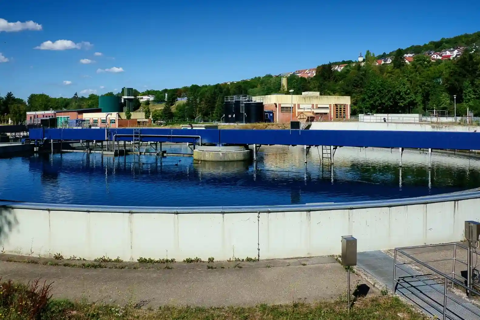
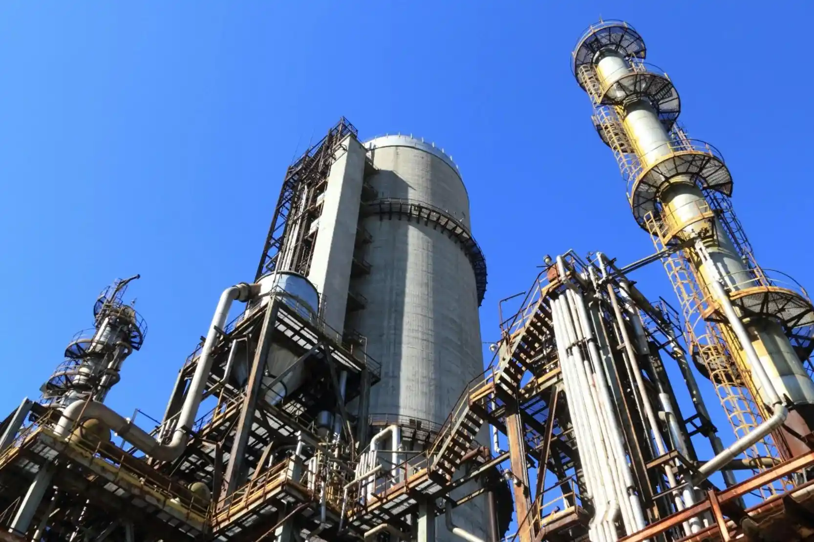
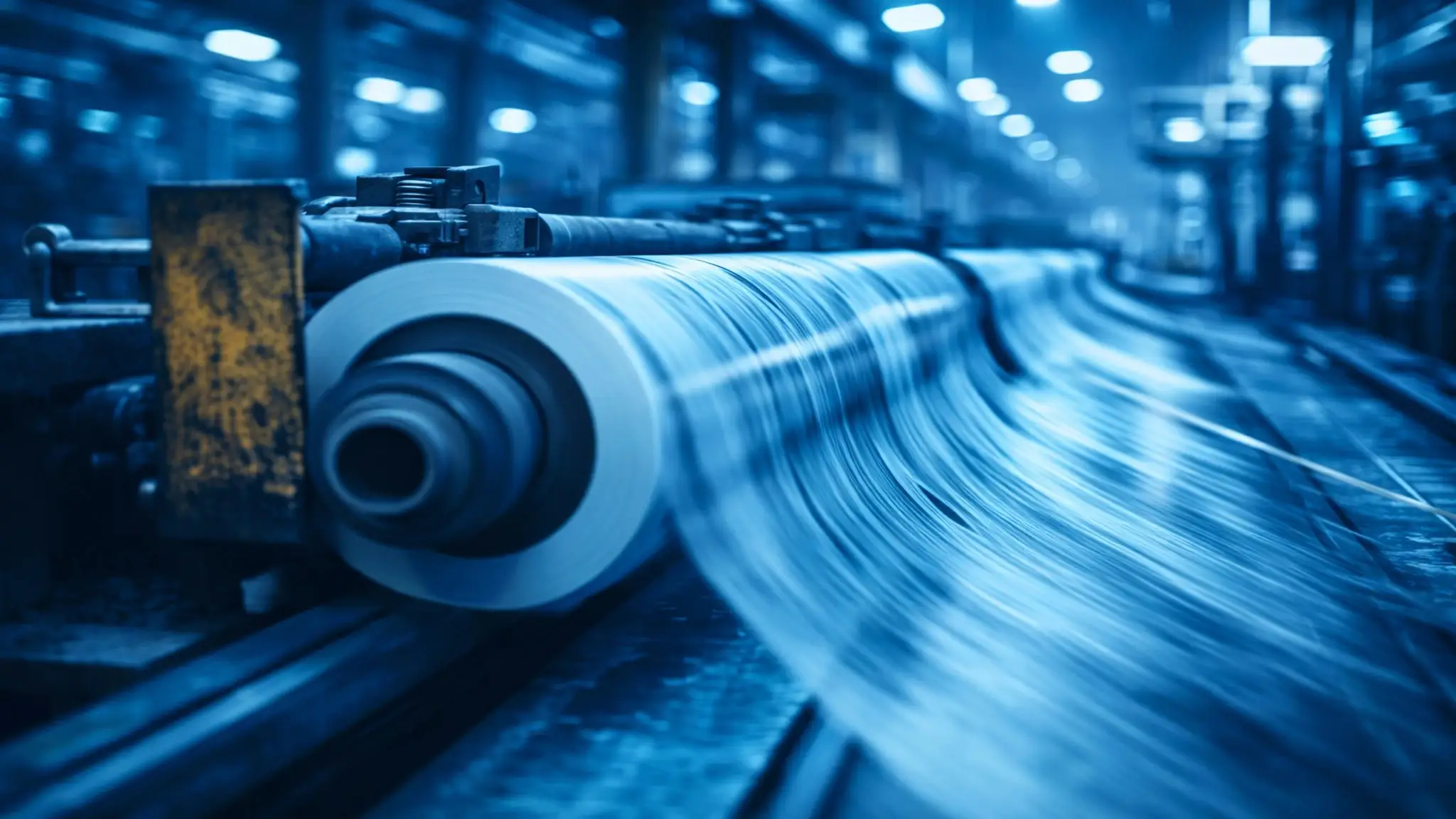
Applications

.webp)


Frequently Asked Questions
What is a flare gas recovery system and how much can it reduce flaring?
A flare gas recovery system (FGRS) captures, compresses, and redirects gas that would otherwise be flared, returning it to the fuel gas system or process. Properly designed FGRS can reduce routine flaring by 80–98%, leaving the flare available only for genuine upset and emergency events.
How it works:
- Liquid ring or screw compressors draw gas off the flare header below the water seal
- Recovered gas is cooled, dehydrated, and conditioned to fuel-gas quality
- Gas is returned to the plant fuel gas system, refinery gas plant, or process
- Flare remains immediately available for any flow exceeding compressor capacity
The result is a major reduction in routine flaring, lower CO₂ and methane emissions, and recovery of valuable hydrocarbons that would otherwise be destroyed.
How does FGRS recover gas without compromising flare safety?
FGRS preserves flare safety by controlling flare header pressure rather than blocking flow to the flare. Compressors draw gas at a setpoint slightly above the flare seal water level; any flow that exceeds compressor capacity passes immediately to the flare without delay or pressure buildup.
Safety design principles:
- Water seal between flare header and compressor isolates the systems
- Pressure control modulates compressor capacity, never restricts header flow
- Compressor failure trips the system to free-flare mode automatically
- Bypass and shutdown logic ensure relief always reaches the flare during upsets
- Header pressure stays within design range during all operating modes
Result: routine flaring is recovered, but the flare's emergency relief function remains uncompromised. Process safety case is preserved.
What's the typical payback period for an FGRS investment?
Typical FGRS payback is 1–4 years, depending on baseline flare gas volumes, fuel gas value, and applicable carbon credit or regulatory drivers. Sites with high routine flaring and high fuel gas value see the fastest payback; sites with low baseline flaring may need regulatory drivers (carbon pricing, flaring restrictions) to justify investment.
Payback drivers:
- Baseline flare gas volume — higher flow = faster payback
- Fuel gas displacement value — recovered gas offsets imported or produced fuel
- Avoided steam consumption (where flare uses steam-assist)
- Carbon credits or compliance with flaring reduction regulations
- Avoided emissions penalties under regional regulations
For continuous-operation refineries with significant routine flaring, FGRS is often among the highest-ROI environmental projects on the asset.
What gas flow rates and pressures can FGRS handle?
FGRS units handle gas flows from a few hundred kg/hr to 50,000+ kg/hr at suction pressures typically 5–50 mbarg above atmospheric, matched to the flare header design pressure. Compressors are sized for the routine flare gas profile, not the peak relief case.
Sizing inputs:
- Routine flare gas flow — typical 95th-percentile of historical data
- Composition variability — affects compressor selection and discharge cleanup
- Suction pressure range — matched to flare header low-pressure operation
- Discharge pressure — matched to fuel gas or process tie-in target
- Turndown requirement — multiple compressors or VFD drives provide flexibility
Multiple parallel compressors are common for redundancy and to match variable load profiles, with one or two units cycling on and off as flow varies.
How does FGRS integrate with an existing flare header?
FGRS integrates with an existing flare header through a tie-in upstream of the flare's water seal, with the recovery compressor maintaining a small positive suction. The flare and its header remain unchanged; only the gas path before the seal is modified to allow recovery.
Typical retrofit scope:
- New tie-in point on the flare header (above water seal)
- Compressor skid with knockout drum, cooler, dehydration, and controls
- Discharge piping to fuel gas system or process tie-in
- Pressure control logic integrated with the plant DCS
- Bypass and shutdown logic to ensure flare availability during compressor outage
- Updated relief case analysis and process safety review
Retrofits typically require a brief plant shutdown for tie-in, scheduled with planned maintenance to minimize impact.
What does FGRS do during upset and emergency conditions?
During upset or emergency conditions, FGRS automatically relinquishes flow to the flare: when relief flow exceeds compressor capacity, header pressure rises briefly, the water seal breaks, and gas flows directly to the flare. The compressor continues recovering whatever fits within its capacity.
Operating modes:
- Normal: 100% of routine flare gas recovered; flare pilot only
- Minor upset: compressor at full capacity; small excess goes to flare
- Major upset/emergency: water seal breaks; full relief flows to flare; compressor continues recovering background flow
- Compressor trip: all flow goes to flare; recovery resumes when compressor restarts
The flare's emergency relief function is never compromised — FGRS is a parallel recovery path, not a series device.
What standards and emissions reductions are typical for FGRS?
FGRS designs follow API 521, API 537, API 619, API 618, API 11P (compressors), and applicable pressure-vessel codes (ASME). Emissions reductions are significant: a properly designed FGRS reduces routine flaring by 80–98%, cutting CO₂, methane, and hydrocarbon emissions proportionally.
Typical emissions impact:
- CO₂ reduction proportional to recovered gas volume and carbon content
- Methane emission reduction (if any methane slip from flare combustion)
- Reduced thermal NOx from lower flare burn rates
- Lower visible flare activity, reducing community impact
- Potential carbon credit eligibility under voluntary or regulatory frameworks
Performance is verified through pre/post flare gas metering, with compliance reporting tied to local environmental regulations and corporate sustainability targets.