
Open Elevated Flare
Safe, Reliable, and Robust Combustion with Open Elevated Flare Systems
.svg)
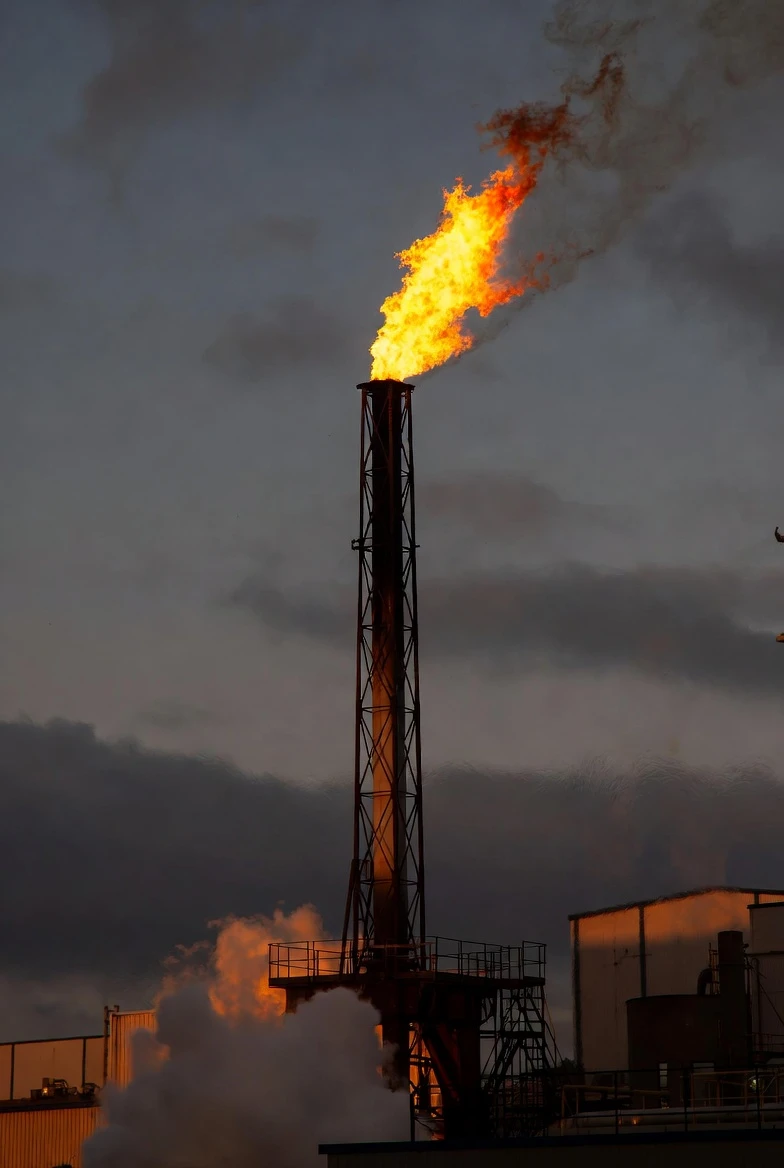
Safe elevated combustion for routine venting and emergency relief
CRA’s Open Elevated Flare systems ensure safe, efficient combustion of waste gases during routine or emergency events. Offered in unassisted, air-assisted, and steam-assisted designs, they provide smokeless operation across diverse gas compositions. High-performance flare tips and optional windshields deliver stable, efficient flames in varying conditions. Built with durable materials, automated controls, and safety-certified features, they offer reliable, low-maintenance performance.
Destruction Efficiency
>98%
Assist Options
3 types
Pilot
Automated
Standard
API 537
What is a Open Elevated Flare?
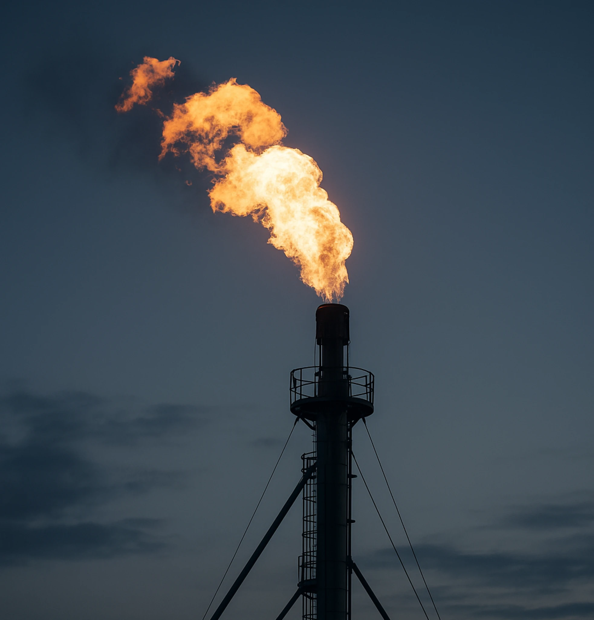
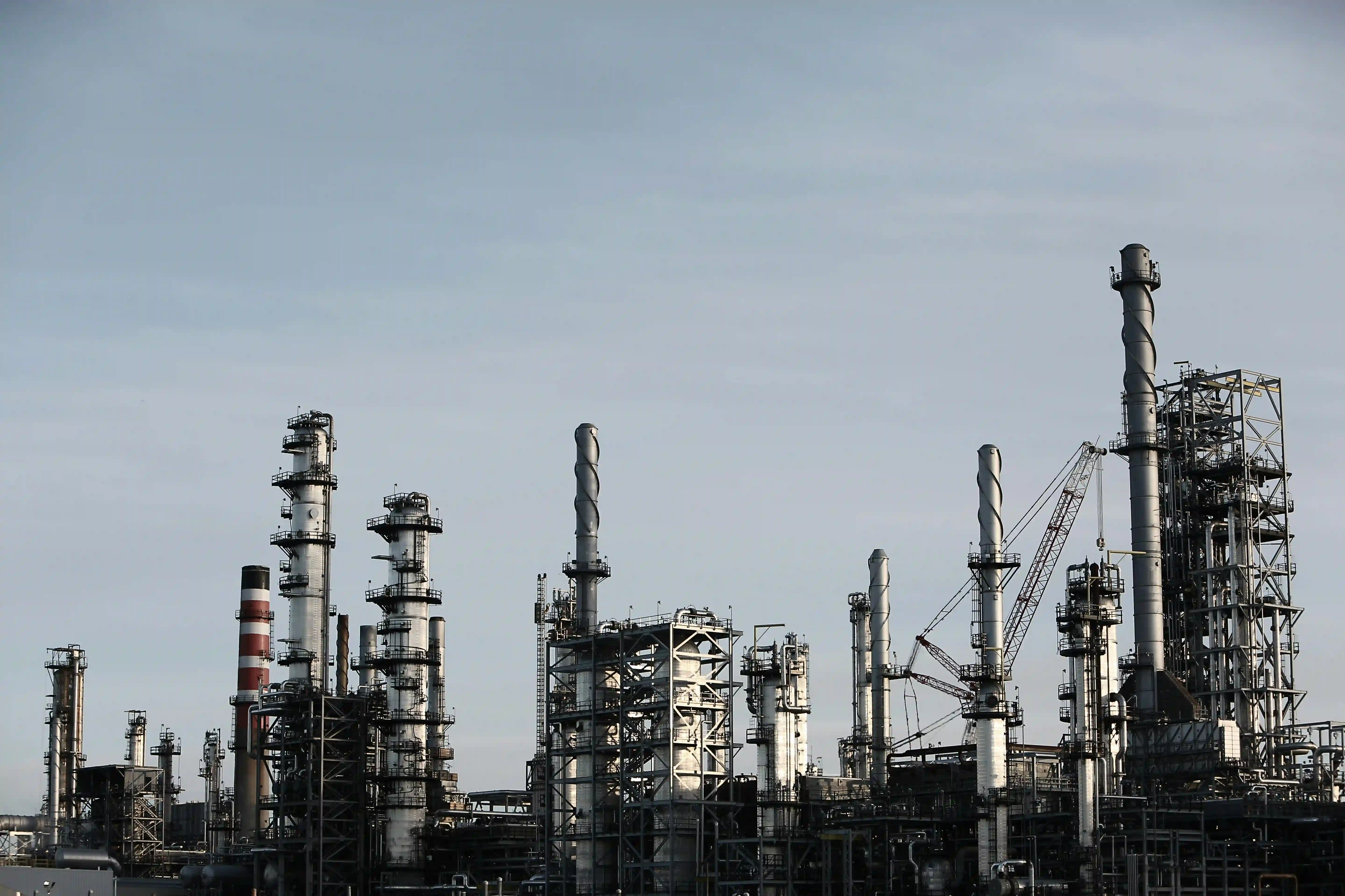
An open elevated flare is a combustion system mounted at height on a dedicated stack, designed to disperse combustion products safely above ground level and away from plant personnel, equipment, and site boundaries — serving as the primary safety relief and routine venting system for oil and gas, refinery, and chemical plant operations.
How it works
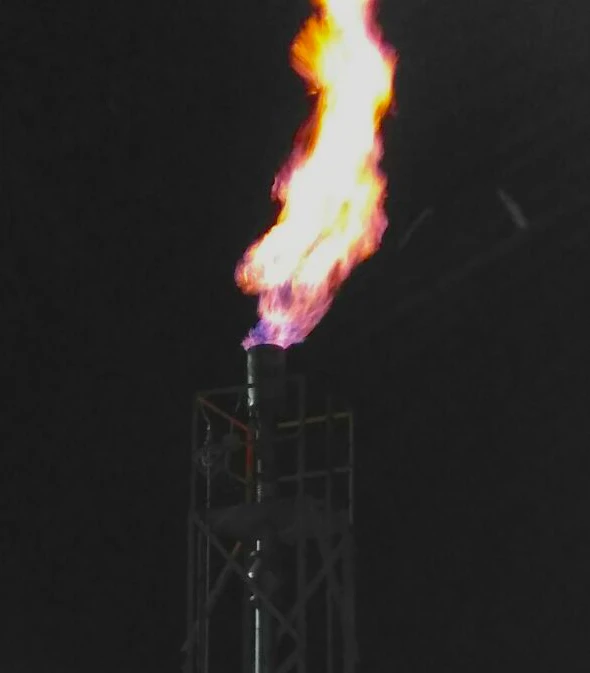
Waste gas travels up the stack and burns continuously at the tip, with stack height and tip design set by the gas composition and flow conditions at that specific site.
Waste gas travels up the flare stack to the tip, where an always-lit pilot maintains continuous ignition.
Discharge height keeps thermal radiation at grade within safe limits and gives combustion products room to disperse into the atmosphere.
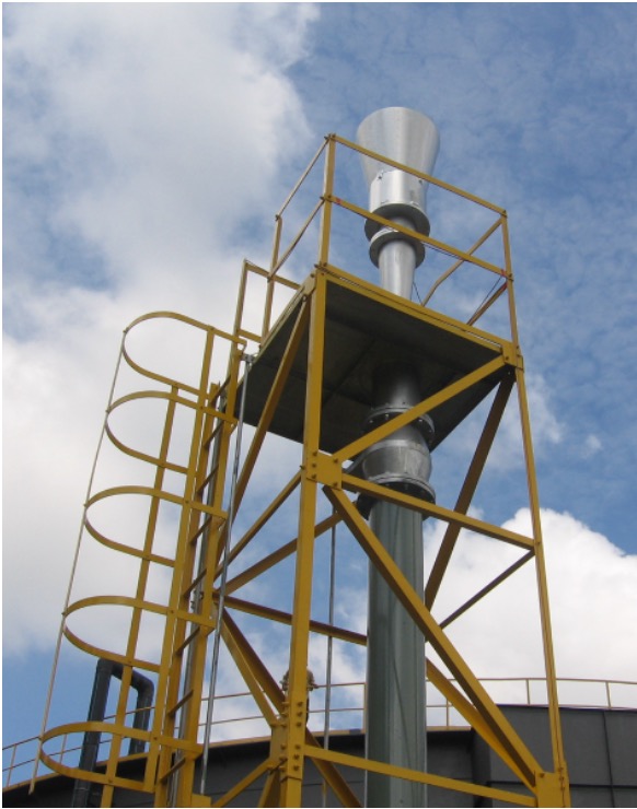
Tip design, unassisted, air-assisted, or steam-assisted, is chosen based on the gas composition, smokeless requirement, and flow range of the specific application.
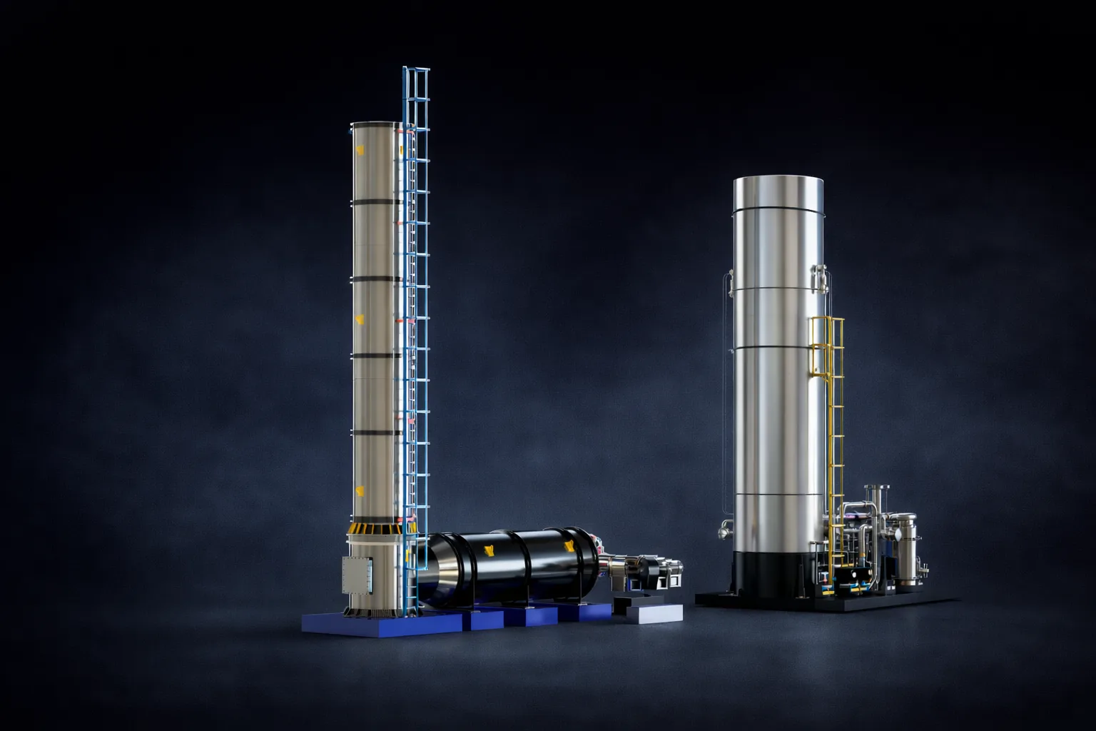
CRA engineers the tip, stack, knockout drum, liquid seal, purge system, and ignition as one system, sized to site-specific process conditions.
Key Benefits
Elevated design ensures safe dispersion of heat and combustion products, protecting plant personnel and equipment
Capable of managing variable gas loads, from pilot flows to large emergency relief conditions
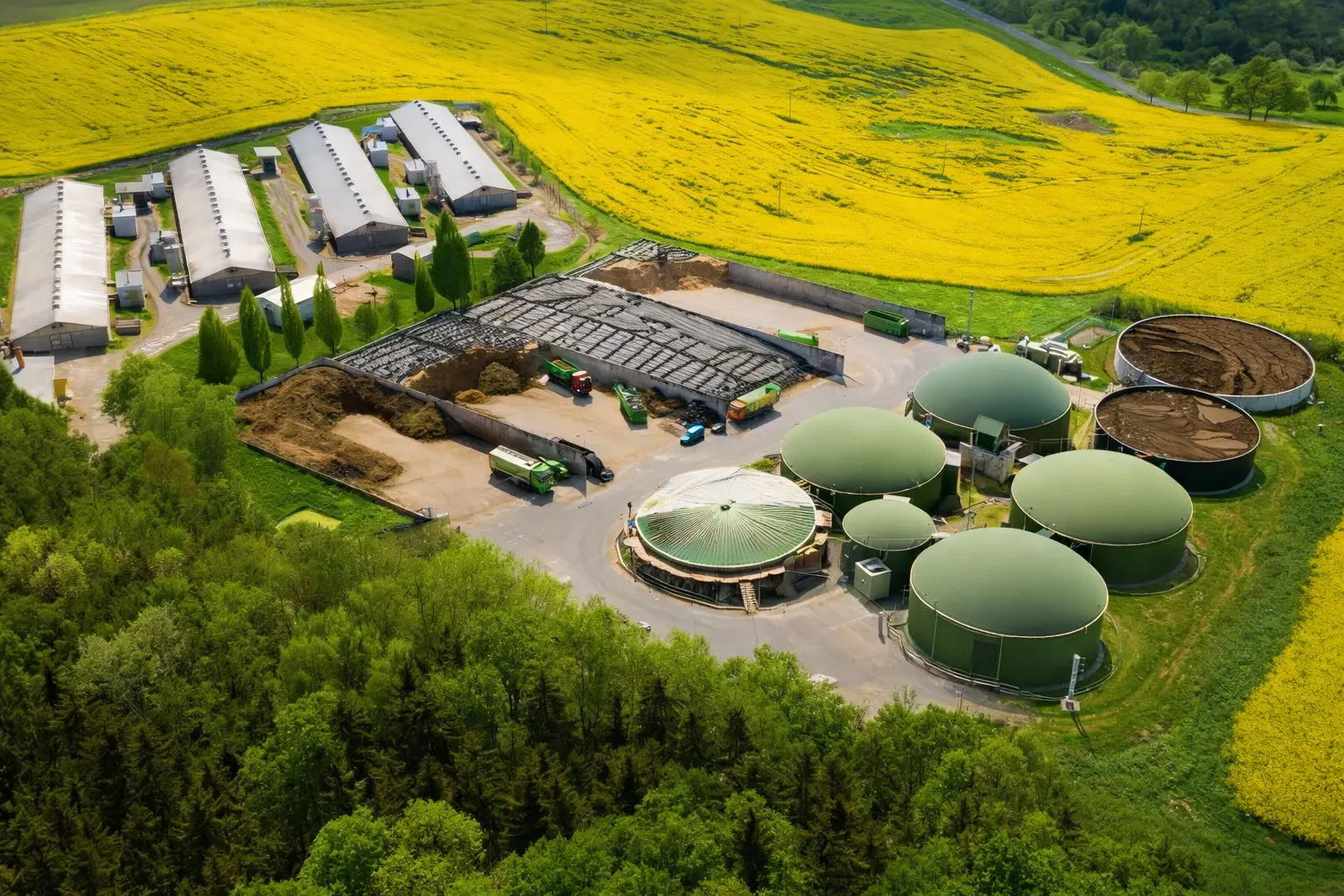
CRA offers proprietary flare tips and windshields engineered to enhance flare performance, durability, and reliability in biogas applications
Rugged design, advanced flame stabilization, and durable materials extend service life with minimal upkeep
Designed to meet or exceed API 537, EPA 40 CFR 60.18, and international flare regulations
Projects That Push Boundaries
Covers both routine surplus and emergency relief biogas under a single compliant system.
.webp)
Handles purge-only to full emergency relief at 358 t/hr with minimised purge gas consumption.
Smokeless performance CFD-validated, with built-in ignition redundancy for uninterrupted field operation.
The CRA Edge
Over 30 years of experience in gas handling and flare engineering
End-to-end design, R&D, and manufacturing under one roof for speed and quality
ISO 9001, ASME Standards, API, and CE
CFD & simulation-driven design, precise fabrication, and unmatched long-term support
Applications

.webp)


.webp)

Frequently Asked Questions
When is an open elevated flare the right choice?
Open elevated flares are the right choice for high-volume relief and emergency service where the gas flow can far exceed normal venting rates and elevation is required to disperse heat and combustion products safely away from personnel and equipment. They're the standard for refinery and petrochemical flare headers.
Best fit when:
- Peak relief flows are very high (e.g., refinery main flare, vessel blowdowns)
- Heat dispersion at elevation is needed for personnel safety
- Plant footprint is too constrained for an enclosed ground flare at peak flow
- Flame visibility is acceptable for the site (industrial location, no community impact constraints)
- Wide operating range from pilot flow to large emergency relief
For sites near residential areas or where flame visibility is unacceptable, enclosed ground flares are preferred.
What turndown ratio can open elevated flares achieve?
Open elevated flares can achieve turndown ratios of 100:1 or higher when designed with multi-stage flare tips and proper pilot systems. This wide range is what makes them suitable for handling everything from continuous low-flow venting to massive emergency relief in a single device.
How it's achieved:
- Continuous pilot flame ensures ignition reliability at lowest flows
- Multi-tip or staged-tip design distributes peak flow across multiple combustion points
- Purge gas system maintains positive pressure in the stack to prevent air ingress at low flow
- Tip geometry is optimized for stable flame across full velocity range
Wide turndown is critical for refinery applications where the same flare must handle routine fugitive emissions and 100+ kg/s upset relief.
How does an elevated flare ensure safe heat dispersion?
Elevated flares disperse combustion heat by burning the gas at a height above the surrounding plant, allowing thermal radiation and hot combustion products to dissipate before reaching personnel-accessible areas. Stack height is calculated specifically to keep ground-level radiation within safe limits during peak relief.
Design considerations:
- API 521 radiation limits — typically 1.58 kW/m² (500 BTU/hr·ft²) for personnel areas
- Stack height calculated for worst-case relief and ambient wind conditions
- Exclusion zone defined around the base for radiation and dispersion safety
- Tip design controls flame length, lift-off behaviour, and direction
- Optional windshield or shroud improves flame stability in high-wind sites
Design verification uses radiation and dispersion modelling to confirm safety distances under worst-case conditions.
What are the differences between unassisted, air-assisted, and steam-assisted elevated flares?
Open elevated flares are available in three configurations based on how smokeless combustion is achieved on heavy or fuel-rich streams.
- Unassisted (utility) — simplest design, lowest cost. Used when waste gas burns smokeless on its own (light hydrocarbons, hydrogen-rich gas) or where smoke is not a regulatory concern.
- Air-assisted — blower injects combustion air for smokeless burn of heavy hydrocarbons. Best when steam isn't available or for moderate flows where steam-assist would be over-engineered.
- Steam-assisted — high-pressure steam injection enables smokeless combustion at the highest flows. Standard in refineries and petrochemical plants where steam is already available; offers the highest smokeless capacity.
Selection depends on gas composition, peak flow, available utilities, and emissions requirements. CRA evaluates all three during early design.
What standards do open elevated flares meet?
Open elevated flares are designed to meet API 537 (flare design), API 521 (relief and depressuring systems), and EPA 40 CFR 60.18 (control device requirements). International projects add EU IED, ATEX (where applicable), and local environmental standards.
Key compliance items:
- Tip exit velocity within smokeless and stable-flame limits
- Net heating value of combustion zone gas above regulatory minimum
- Continuous pilot monitoring with redundant ignition
- Radiation calculations confirming personnel-safe ground levels
- Structural design per ASME and applicable wind/seismic codes
Manufacturing follows ISO 9001 and CE; API certification is included where required by project specs.
How are open elevated flares used in LNG and petrochemical service?
In LNG and petrochemical service, open elevated flares handle large emergency relief volumes from compressors, storage tanks, and process units, while also covering routine purge and vent flows. The combination of wide turndown and large peak capacity makes them the standard relief device for these industries.
Typical service:
- LNG storage tank and ship-loading vapour relief
- Compressor and turbine blowdown during start-up, shutdown, or trip
- Process unit relief from reactors, distillation columns, separators
- Pipeline and pig-launcher depressuring
- Routine purge gas to prevent air ingress in the flare header
Materials and tip design are selected for the specific gas mix; sour or acid service requires upgraded metallurgy and corrosion-resistant tip components.
What's the typical service life of an elevated flare structure?
An elevated flare structure (stack and supports) typically lasts 25+ years with proper maintenance, while wear components like the flare tip, pilot system, and ignition components have shorter service lives and are designed to be replaced.
Component service life:
- Stack and structural supports — 25+ years; carbon steel with periodic recoating
- Flare tip — 10–15+ years depending on service severity (sour, acid, high-temperature streams shorten life)
- Pilot burners and ignition — 5–10 years; replaceable items
- Steam or air injection components — 10–15 years
- Purge reduction seals — 10+ years; refurbishable
Long-term service agreements and scheduled inspections extend overall system life and prevent unplanned failures.