
Landfill Gas Flare
Built for the Full Life of a Landfill Gas Field
.svg)
Enclosed combustion built for a landfill gas field's changing flow and gas chemistry
CRA’s Landfill Gas Flares are engineered for the operating realities of a municipal solid waste site, where gas flow falls steadily as a cell ages and composition shifts with moisture, hydrogen sulphide, and siloxane content. High turndown ratios keep combustion stable from early peak generation through decades of gradual decline. Corrosion-resistant material selection protects the flare stack and internals against H2S and moisture attack, extending service life without added maintenance. Integrated odour and VOC control keeps the system compliant as landfill gas composition changes over the site's operating life.
Destruction Efficiency
>98%
Turndown Ratio
100:01:00
Construction
Corrosion-resistant, site-matched
Standards
EPA NSPS/EG, API 537
What is a Landfill Gas Flare?
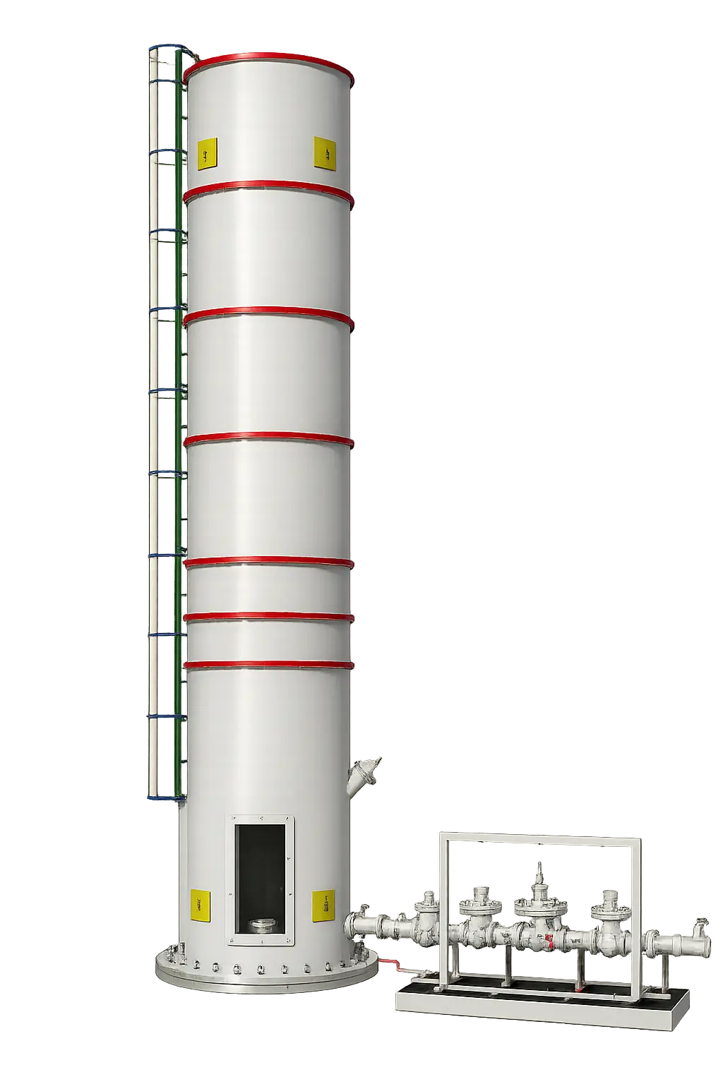
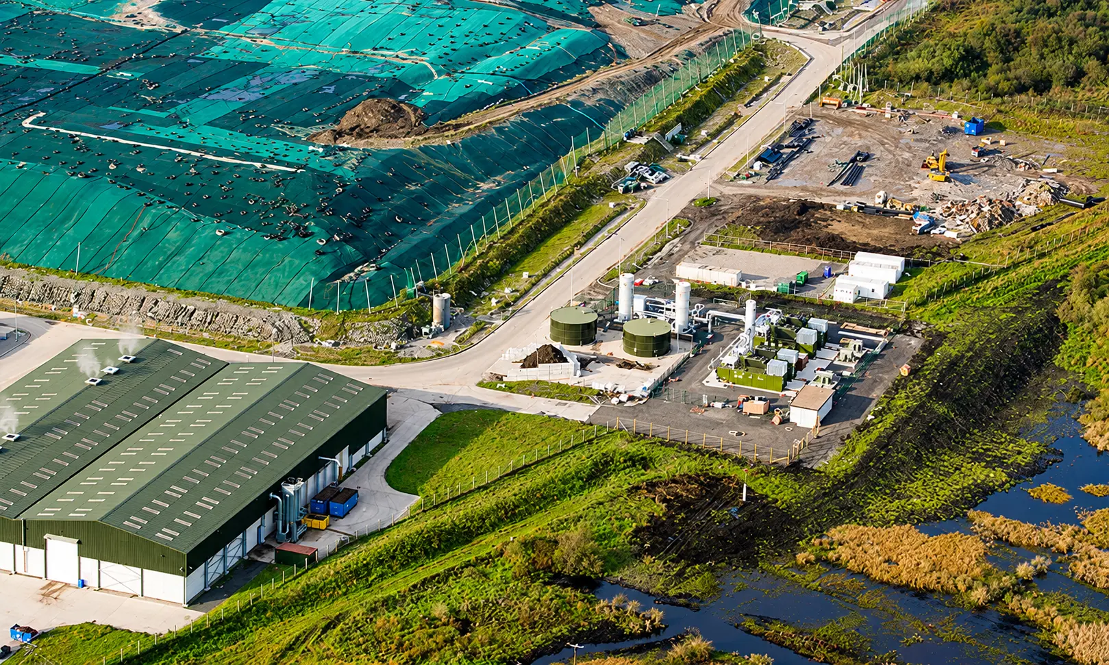
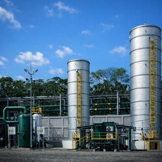
A landfill gas flare is an enclosed, refractory-lined combustion unit that destroys methane, hydrogen sulphide, and other odorous compounds generated by decomposing municipal solid waste, using stable ground-level combustion tuned for gas flow that changes significantly over a landfill's operating life.
How it works
Landfill gas enters the chamber through a control valve and distributes across multiple burners sized for stable combustion despite changing flow and gas composition, fully contained within a refractory-lined enclosure built with materials selected for H2S and moisture resistance.
Landfill gas enters through a control valve and distributes across multiple burners engineered for stable combustion at varying flow rates.
Combustion air enters through controlled inlets at the chamber base, supplying burners evenly across the chamber regardless of load.
Refractory lining holds combustion temperature above the threshold required for high destruction efficiency, keeping the outer shell cool to the touch.
Stack and internal components use alloys and coatings selected for the H2S, moisture, and siloxane content typical of landfill gas, extending service life against corrosion.
An automated control system modulates gas flow from a landfill's peak generation years through its long decline, without manual resizing.
Key Benefits
Stable combustion from a landfill's peak gas generation years through its long decline, without re-sizing or retrofitting the flare.
Automated flow and vacuum control absorb daily and seasonal swings in gas volume across the well field without flame instability.
Material selection accounts for H2S, moisture, and siloxane exposure inherent to landfill gas, protecting the stack and internals against premature corrosion.
Combustion is tuned for the mixed odorous compounds typical of decomposing waste, reducing hydrogen sulphide, mercaptans, and non-methane organic compounds at the source.
Meets EPA NSPS/EG landfill gas control requirements and international destruction efficiency standards for municipal solid waste sites.
Projects That Push Boundaries
.webp)
Enclosed ground flare system for MCGM's Gorai dumpsite closure, commissioned and running without interruption ever since.
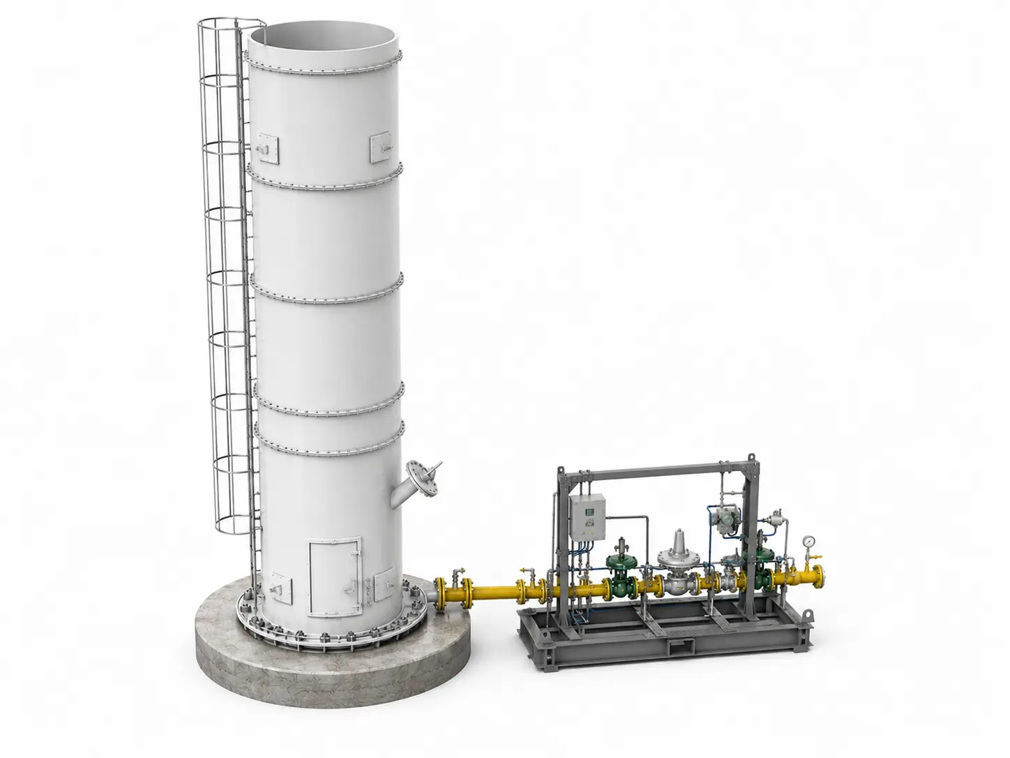
Enclosed flare tower and extraction system handling 600 Nm3/h of landfill gas at DRE above 99%, compliant with CPCB stack limits.
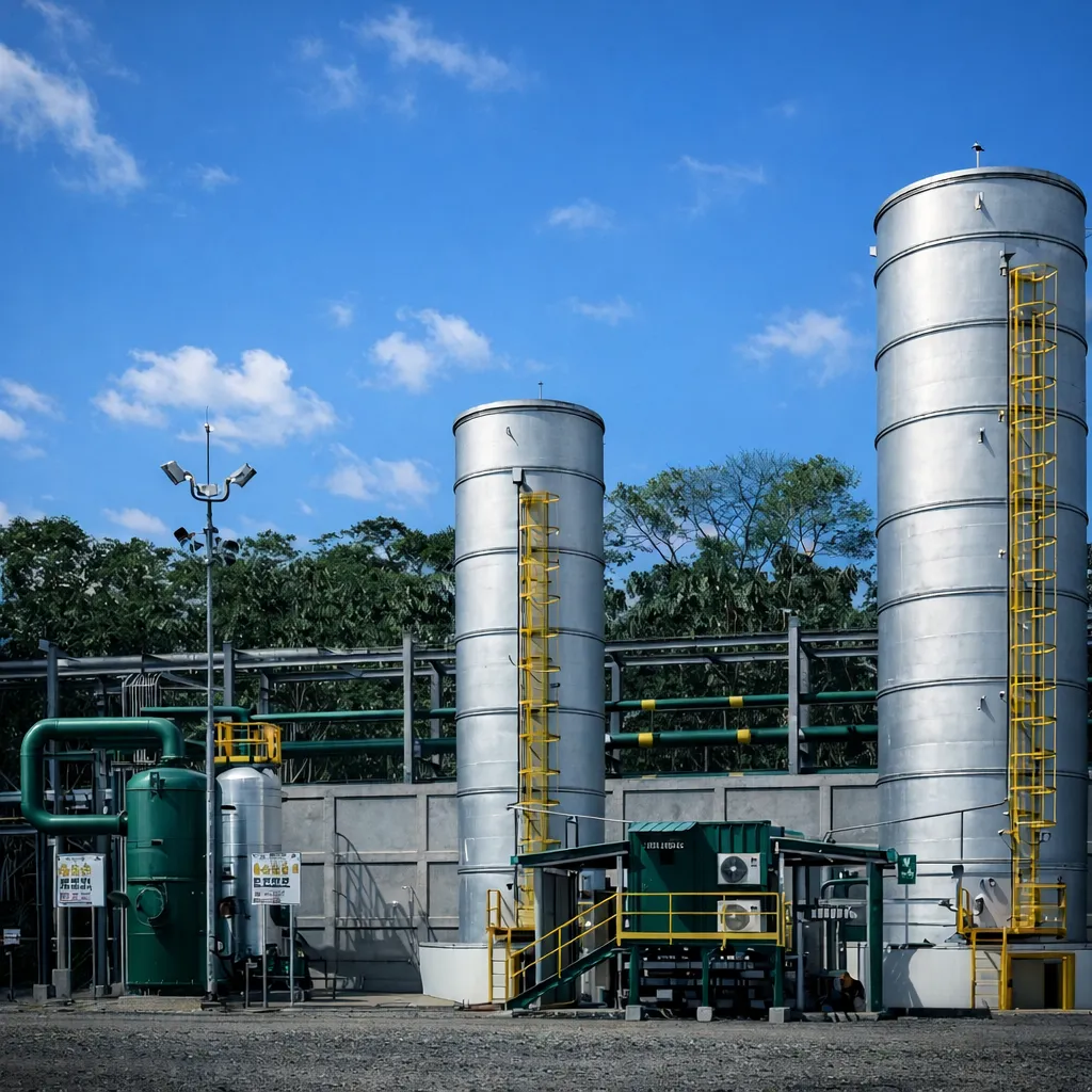
CRA's first Sub-Saharan Africa landfill gas installation, delivered under a single contract from design through commissioning.
The CRA Edge
Delivered enclosed flare systems for municipal solid waste sites across multiple geographies, including Gorai (Mumbai), Ghazipur (Delhi), and Repi (Addis Ababa).
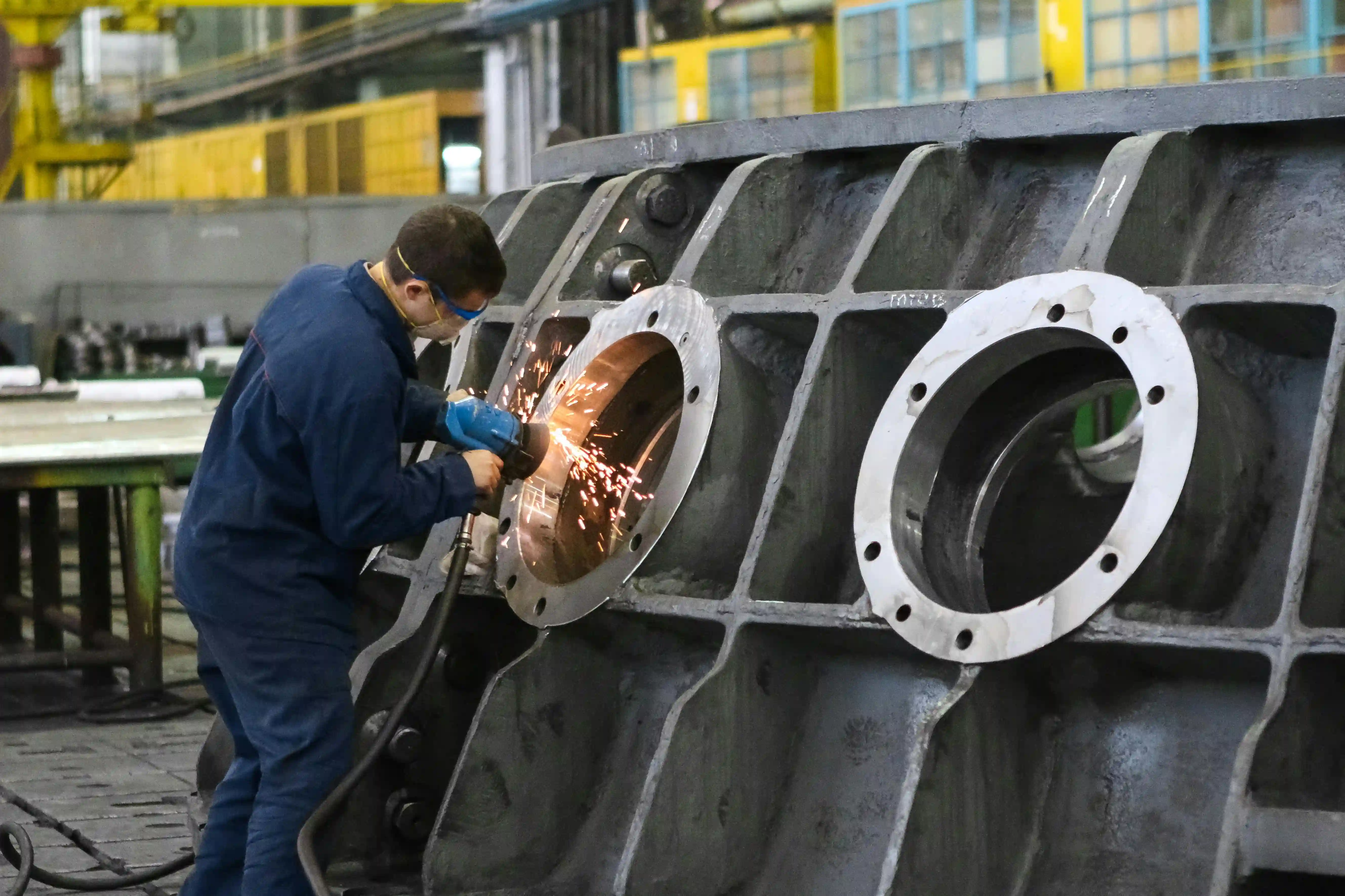
Design, fabrication, and controls integration handled under one roof, from CFD-modeled combustion to site commissioning.
Alloy and coating selection matched to each site's H2S and moisture profile rather than a single default specification.
Systems engineered to meet EPA NSPS/EG, API 537, and international landfill gas emission standards.
Applications

Built to help you specify.
Sizing tools, decision guides, and technical references. Use them before, during, and after your evaluation.



Frequently Asked Questions
What materials prevent corrosion in a landfill gas flare?
Landfill gas is saturated with moisture and typically contains 100 to 2,000 ppm of hydrogen sulphide, along with trace halogenated compounds. Combined, these attack untreated carbon steel over time, particularly at condensate low points and burner internals. Wetted components and burner tips are commonly built in 304 or 316 stainless steel, with coated carbon steel used for the outer stack and structural sections. Material selection is matched to each site's actual gas analysis rather than a single default specification, since H2S concentration and moisture loading vary significantly between landfills.
What standards and regulations apply to landfill gas flares?
Flare design and mechanical construction typically follow API 537 (Flare Details for Petroleum, Petrochemical, and Natural Gas Industries), with pressure-retaining components meeting applicable ASME codes. On the emissions side, US landfills are governed by US EPA NSPS Subpart XXX (new and modified sites) and the corresponding Emission Guidelines for existing sites, both requiring 98% NMOC destruction efficiency or an outlet concentration below 20 ppmv. Sites outside the US typically reference the EU Industrial Emissions Directive (IED) or the equivalent national environmental regulation. API 537 (flare mechanical design and safety); ASME (pressure-retaining component codes); US EPA NSPS Subpart XXX / WWW (landfill gas emission control); EU IED (industrial emissions for EU-based sites).
What destruction efficiency does a landfill gas flare achieve?
Properly designed enclosed landfill gas flares achieve destruction efficiencies above 98% for methane and non-methane organic compounds, meeting the enclosed combustion device threshold set out in US EPA NSPS Subpart XXX and the corresponding Emission Guidelines for existing landfills. Achieving that figure in practice depends on maintaining combustion temperature, residence time, and air-to-fuel ratio across the flare's full turndown range, not just at design flow. Automated control systems that hold these parameters steady as gas volume and composition shift are what keep destruction efficiency consistent over the life of the site.
How is a landfill gas flare sized across a site's operating life?
Landfill gas generation follows a predictable arc: it rises for several years after waste placement, peaks, then declines gradually over decades as the organic fraction is consumed. Sizing a flare only for peak flow leaves it oversized and unstable during the long decline that follows. Sizing starts with a gas generation model built from waste-in-place tonnage, composition, and site-specific decay rates, then checks the flare's turndown range against both the projected peak and the multi-decade tail. Modular or multi-unit configurations are used where a single flare cannot cover the full range, or where phased cell development means gas volume arrives in stages rather than all at once.
How does a landfill gas flare control hydrogen sulphide and other odours?
Landfill gas carries hydrogen sulphide, mercaptans, and a range of non-methane organic compounds (NMOCs) produced as municipal solid waste decomposes. These compounds are the source of the odour associated with active and recently closed cells. An enclosed flare destroys them through sustained high-temperature combustion inside a refractory-lined chamber, typically operating above 870°C with a residence time of at least 0.3 seconds. US EPA guidance requires enclosed combustion devices for landfill gas to reduce NMOC by at least 98% by weight, or to an outlet concentration below 20 ppmv as hexane. Burner and chamber design account for the specific mix of odorous compounds in landfill gas rather than treating it as a generic methane stream.