
Dry Iron Scrubber
Iron Oxide Media, Engineered for High H2S Duty
.svg)
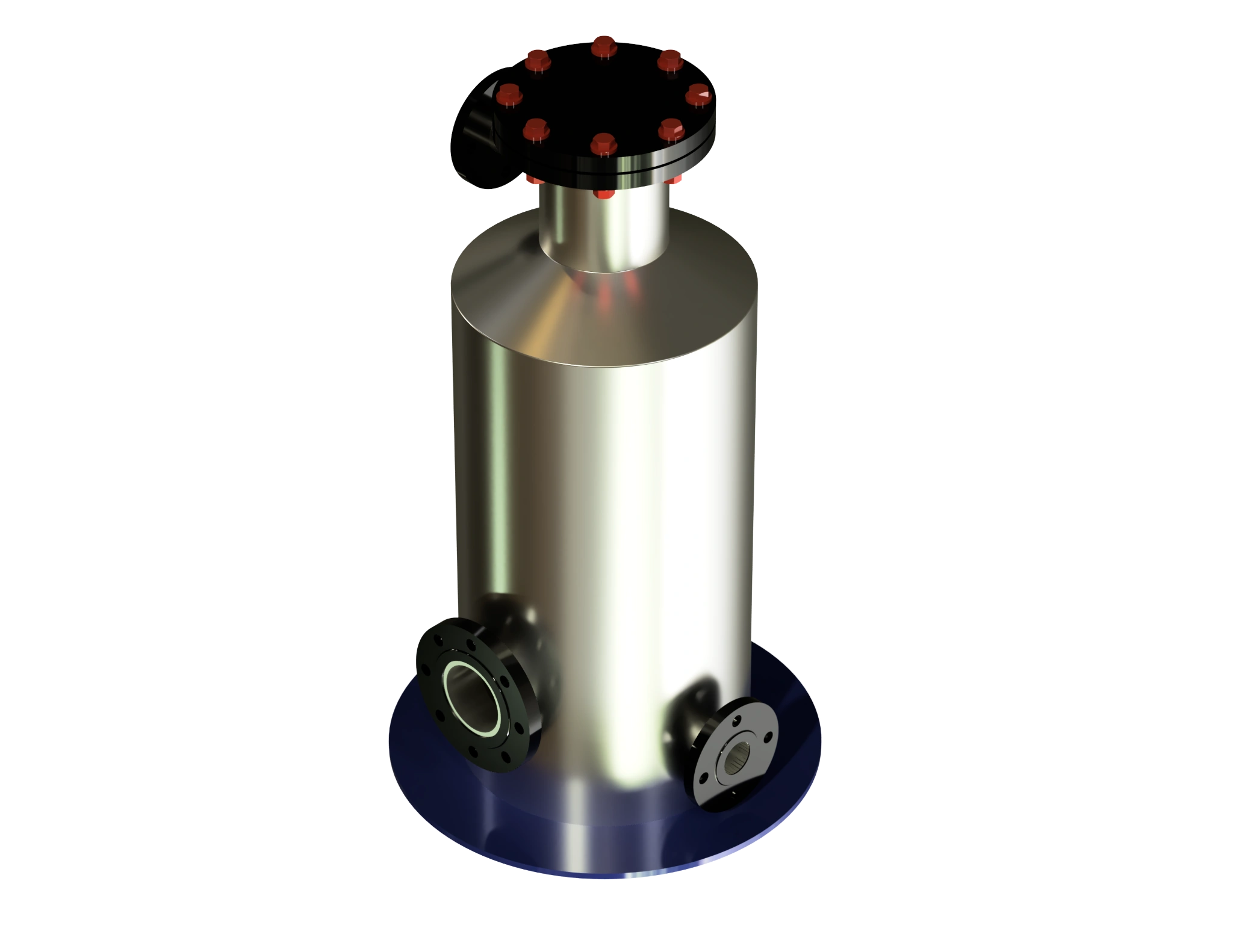
H2S Removal Engineered Around Impregnated Iron Oxide Media
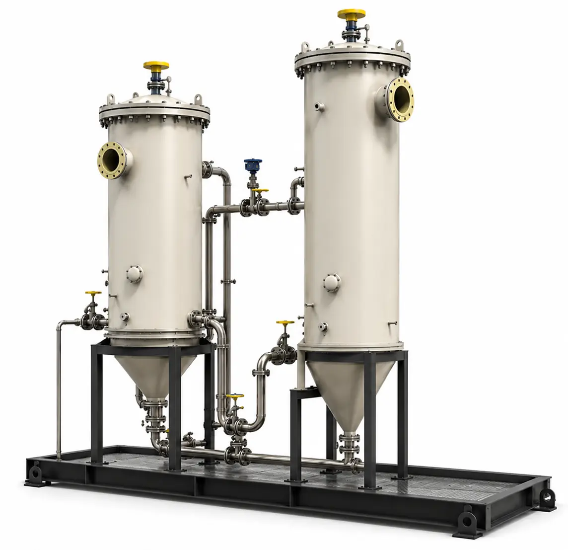
CRA's Dry Iron Scrubbers use impregnated iron oxide media to strip H2S from biogas, landfill gas, and associated gas streams at a lower cost per pound removed than activated carbon. Each skid is fabricated in-house to ASME Section VIII Div. 1, with bed sizing calculated against actual site gas composition rather than generic sizing charts. The system targets H2S specifically; it does not remove VOCs, siloxanes, or other organic compounds, and is best suited to applications where H2S is the primary contaminant of concern. A moisture conditioning point ahead of the bed keeps the media within its active reaction range across fluctuating inlet loads.
H2S Removal
Up to 99.9%
Media Type
Impregnated Iron Oxide
Configuration
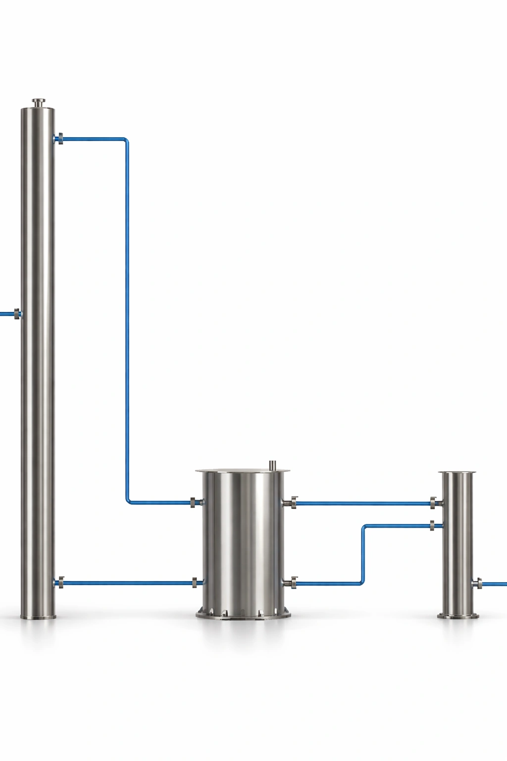
Custom multi-vessel
Vessel Code
ASME Section VIII
What is a Dry Iron Scrubber?
A Dry Iron Scrubber is a fixed-bed vessel that strips H2S from a gas stream by passing it through media impregnated with iron oxide. H2S reacts with the iron oxide to form iron sulfide, which stays trapped in the bed while treated gas exits below the required outlet specification. The process does not filter VOCs, siloxanes, or other organic compounds.
How it works
Raw gas enters the vessel through a distributor plate and passes down through the impregnated iron oxide bed, where H2S reacts with the media to form iron sulfide, while a moisture conditioning point ahead of the bed keeps the reaction active across fluctuating inlet loads before treated gas exits to the downstream flare, engine, or upgrading skid.
Raw gas enters the vessel through a distributor plate that spreads flow evenly across the bed cross-section, preventing channeling.
Gas passes down through the impregnated iron oxide media, where H2S reacts with the iron oxide to form iron sulfide.
A moisture injection point ahead of the bed keeps the media within its active reaction range, since the iron oxide reaction requires bound water to proceed.
Conditioned gas exits below the outlet specification for H2S and routes to the downstream flare, engine, or upgrading skid.
Once the bed is exhausted, spent media is removed through top or side access ports and replaced with fresh charge.
Key Benefits
Impregnated iron oxide media strips H2S at a lower media cost than activated carbon, without paying for adsorption capacity the application does not need.
No moving parts, no rotating equipment, and no chemical dosing system to maintain across the life of the skid.
The fixed bed absorbs day-to-day and seasonal swings in inlet H2S concentration without process upset, though bed life shortens as loading increases.
Spent media is removed and replaced through top or side access ports, typically achievable within a single working shift.
Dry media handling avoids the solvent or liquid waste disposal requirements that come with wet scrubbing alternatives.
The CRA Edge
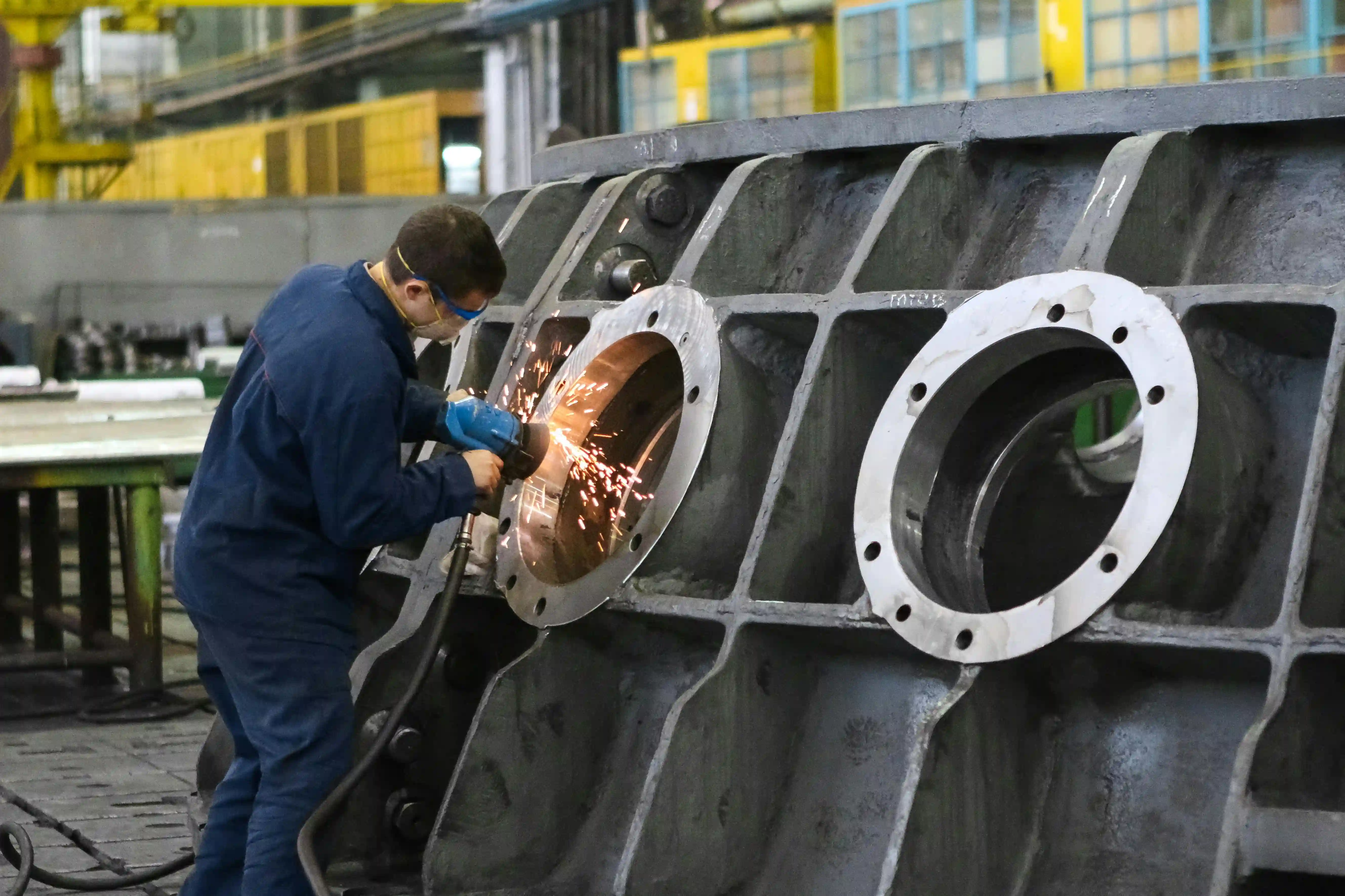
Vessel design, media loading, and controls integration handled under one roof, from ASME-code fabrication to site commissioning.
Bed volume and change-out interval are calculated against each site's actual H2S loading and gas flow rather than a standard catalogue size.
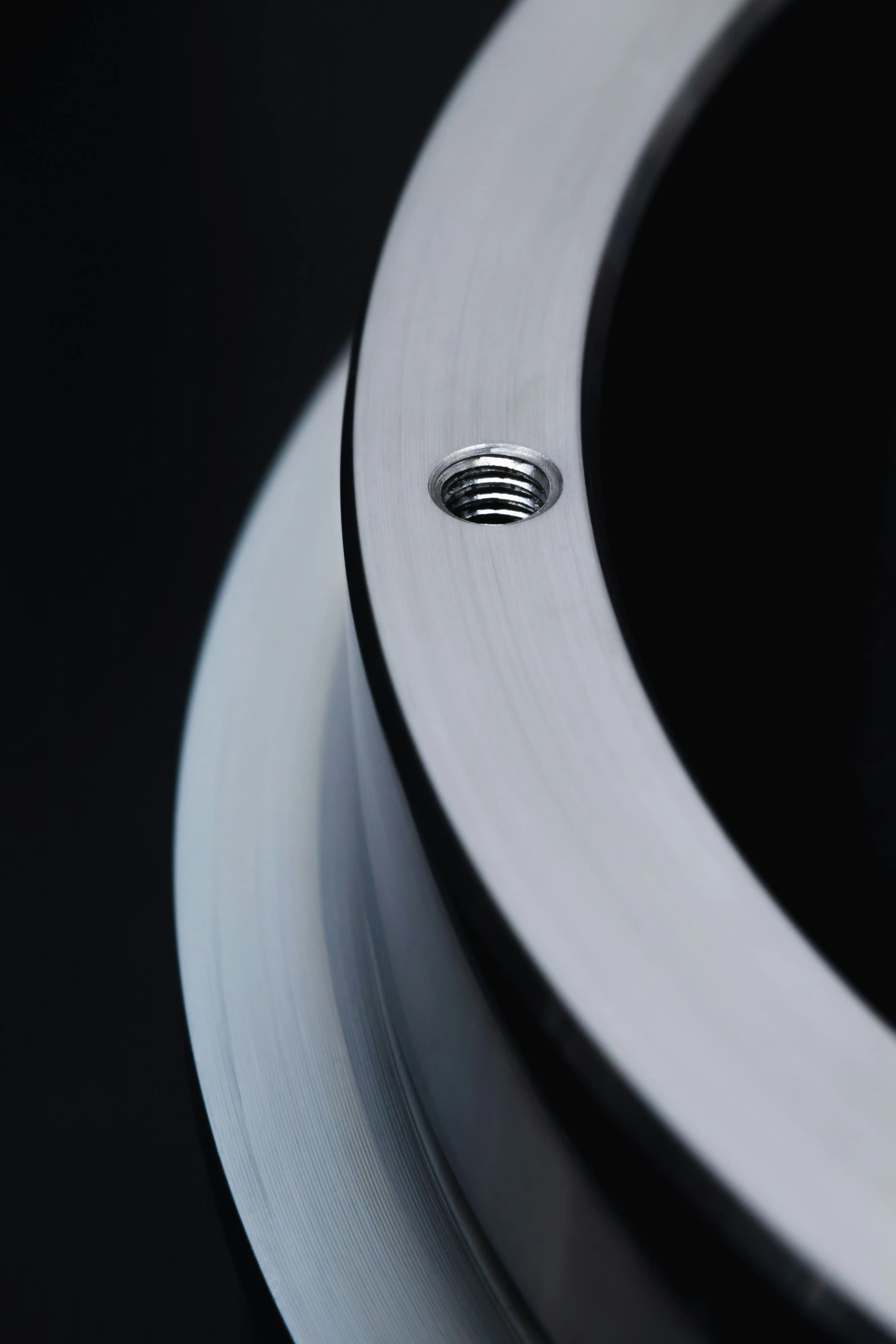
Every vessel is built to ASME Section VIII Div. 1, independent of the media technology inside it.
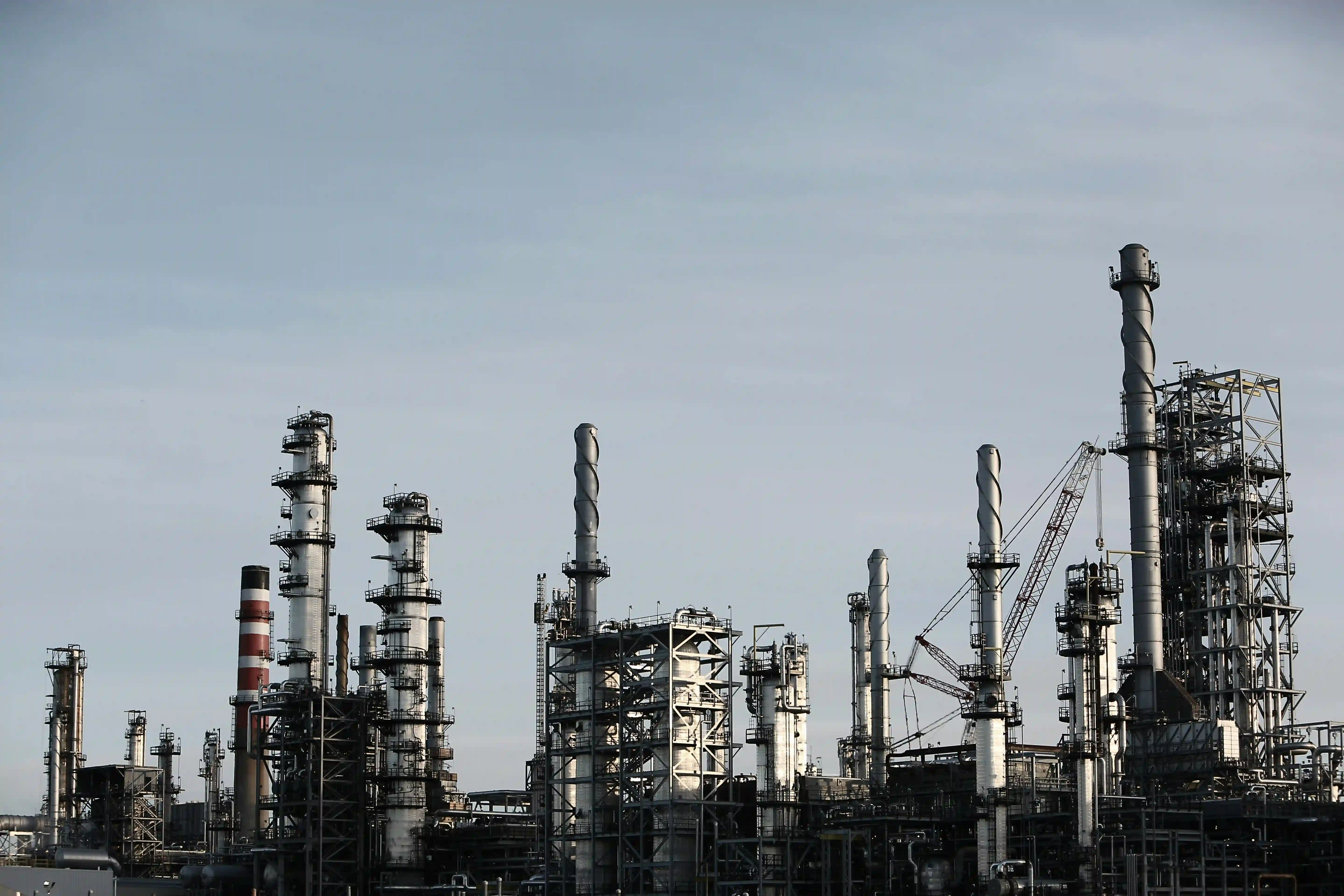
Delivered gas conditioning and treatment skids across biogas, landfill gas, and associated gas applications alongside CRA's flare and compression systems.
Applications


Built to help you specify.
Sizing tools, decision guides, and technical references. Use them before, during, and after your evaluation.




.webp)

Frequently Asked Questions
What does a dry iron scrubber remove from biogas?
A dry iron scrubber uses impregnated iron oxide media to strip hydrogen sulfide (H2S) specifically from biogas, landfill gas, or associated gas streams; it does not remove VOCs, siloxanes, or other organic compounds, so it's best suited to applications where H2S is the primary contaminant of concern. Where multiple contaminants need treatment, a dry iron scrubber is typically paired with other conditioning steps rather than used alone.
How does a dry iron scrubber compare to activated carbon for H2S removal?
Impregnated iron oxide media strips H2S at a lower media cost per pound removed than activated carbon, since activated carbon's adsorption capacity is priced for a broader range of contaminants the application may not actually need. The trade-off is that iron oxide is H2S-specific, so if VOCs or siloxanes are also present, activated carbon or another technology needs to handle those separately.
How long does the iron oxide media last before change-out?
Media life depends on the site's actual H2S loading and gas flow, which is why CRA calculates bed sizing and change-out interval against the specific site's gas composition rather than a generic sizing chart; bed life shortens as H2S loading increases. Spent media is removed and replaced through top or side access ports, typically achievable within a single working shift.
Does a dry iron scrubber need any liquid waste handling?
No. Dry media handling avoids the solvent or liquid waste disposal requirements that come with wet scrubbing alternatives, since spent iron oxide media is handled and disposed of as a solid. A moisture conditioning point ahead of the bed keeps the media within its active reaction range across fluctuating inlet loads.
What pressure vessel code are CRA's dry iron scrubbers built to?
Every dry iron scrubber skid is fabricated to ASME Section VIII Division 1, independent of the media technology inside it, with vessel design, media loading, and controls integration all handled in-house. This applies whether the unit is a standalone polishing step or the primary H2S removal ahead of flaring, CHP engines, or RNG upgrading membranes.