Enclosed Ground Flares: How They Work, How They Are Designed, and How to Specify One

.svg)
An enclosed ground flare burns waste gas inside a refractory-lined chamber at ground level. The flame is hidden, radiant heat and noise stay inside the shell, and the combustion temperature can be controlled and measured. That last point is what separates it from an open flare: the performance of an enclosed flare can be demonstrated, not assumed.
Enclosed ground flares are the standard way to dispose of landfill gas, biogas and off-specification biomethane. They are also used in refining, chemicals, pyrolysis and gas processing wherever a visible flame, a large sterile area or unverifiable emissions are not acceptable.
This article explains how an enclosed ground flare works, how its combustion temperature, residence time and turndown are chosen, and what makes some gases harder to burn than others. It sets out the emission standards that apply in the main jurisdictions, how compliance is shown, the data a manufacturer needs to design one, and the failure modes that recur in the field.
What an enclosed ground flare is
An enclosed ground flare is a combustion device in which the gas burns inside a vertical cylindrical or rectangular chamber that stands at grade, with combustion air admitted in a controlled way at the base. The UN Clean Development Mechanism’s flaring methodology uses the same distinction: an enclosed flare is one where the gas burns inside an enclosure, an open flare is one where it does not (CDM TOOL06). API Standard 537, the main flare equipment standard for the petroleum, petrochemical and natural gas industries, treats enclosed-flame flares as a separate category, with its own chapter on mechanical details and its own informative annex (API 537 contents).
The term “ground flare” is also used for a different technology, the multi-point ground flare, and the two are often confused. The table below sets out how an enclosed ground flare differs from the other devices it is compared with.
The comparison with a thermal oxidiser is the one that causes most confusion, because the two look alike. A thermal oxidiser is designed around a destruction efficiency for a continuous stream, usually with longer residence time, a forced-draft burner and often a heat recovery section. An enclosed ground flare is designed to dispose safely of whatever gas arrives, across a wide range of flow and composition, and to start quickly when it is called on. Where a process needs both, the oxidiser does the continuous abatement and the enclosed flare provides the safe disposal route when the oxidiser trips (CRA: Thermal Oxidizer and Enclosed Ground Flare).
How it works: the gas path from inlet to stack
Gas passes through a short train of protective equipment before it reaches the burner, then burns in the chamber while a temperature loop adjusts the combustion air. In the order the gas meets them:
Knock-out vessel. Removes condensate and entrained liquid. Landfill gas and biogas arrive saturated and cool in the pipework, and liquid reaching the burner causes flame instability and corrosion.
Flame arrester. Stops a flame front travelling back from the burner into the gas line. It is chosen for the gas group and for whether it must stop a deflagration or a detonation, which depends on the pipe run between the ignition source and the arrester.
Isolation and slam-shut valves. A fail-closed automatic valve isolates the gas on any trip, so that no unburnt gas enters a chamber without a proven flame.
Booster blower. Needed where the supply pressure cannot overcome the pressure drop of the train and burner, which is the usual case for digester gas at a few tens of millibar. On landfill gas duty, UK guidance treats a blower rated for explosive atmospheres as essential (EA/SEPA flaring guidance).
Inlet instrumentation. Flow, methane and oxygen at a minimum. Methane shows whether the gas is within the flare’s design envelope. Oxygen shows air ingress, which is both an explosion risk in the line and, on a landfill, a sign of over-extraction. UK guidance names methane and oxygen as the minimum inlet measurements (LFTGN05).
Pilot, ignition and flame detection. A pilot burner, usually on LPG or natural gas, is lit and proven before the main gas valve opens. A UV scanner or ionisation probe confirms the flame for as long as the flare runs.
Burner. One or more burner heads at the base of the chamber, distributing the gas so it mixes with the incoming air and burns in a stable flame across the design range of flow and calorific value.
Combustion chamber. A steel shell lined with ceramic fibre modules or castable refractory, tall enough to enclose the flame completely at all times and to give the required residence time above it.
Air dampers. Louvres around the base admit combustion air, drawn in by the natural draft of the hot chamber. Actuated dampers open or close to hold the chamber temperature at its set point.
Not every enclosed flare has actuated dampers. In a fixed-inlet design the air openings are set at commissioning, and the chamber temperature rises and falls with the gas flow and methane content. Fixed-inlet flares are simpler and lower in cost, and suit sites where the permit does not set a minimum combustion temperature. Where it does, as in the UK's 1,000°C requirement, actuated dampers are needed to hold that temperature across the flow range.
Thermocouples and sampling ports. Thermocouples at the height that corresponds to the required residence time feed the temperature loop. Sampling ports higher up allow the exhaust to be tested after combustion is complete.
Control system. Runs the start sequence (purge, pilot, proven flame, main gas), the temperature loop, the trips and the alarms, and in most modern units sends status and faults to a remote operator.
The temperature loop is the heart of the design. More air cools the chamber; less air heats it. The control system trims the dampers to hold the set point as the gas flow and methane content change. If the temperature cannot be held above its low limit, the flare trips rather than running in a condition where it is no longer destroying the gas as designed.
Design basis: temperature, residence time and air
The destruction performance of an enclosed flare is set by how hot the flue gas is, how long it stays hot, and how well the gas and air are mixed before it leaves. The first two are written into regulation; the third is a matter of burner and chamber design.
Temperature and residence time. The most widely used design basis comes from the UK Environment Agency. Enclosed landfill gas flares must be able to achieve a minimum of 1,000°C with 0.3 seconds retention at that temperature, across the likely range of gas composition, or an equivalent validated set of conditions (LFTGN05). The margin is there for the trace compounds in the gas rather than for methane. Landfill gas carries sulphur and chlorine compounds, which the guidance notes will appear in the exhaust as sulphur dioxide, hydrogen chloride and other chlorinated compounds, and it is these and the carbon monoxide burnout that the conditions are chosen for.
Other jurisdictions frame the requirement differently. US rules for landfill control devices set a performance outcome instead of a temperature: an enclosed combustor must reduce non-methane organic compounds by 98% by weight, or bring the outlet concentration below 20 ppmv as hexane, dry, at 3% oxygen (40 CFR 60 Subpart XXX). US hazardous waste rules allow an enclosed combustion device to show compliance either by performance or by a minimum residence time of 0.5 seconds at 760°C (40 CFR 264.1033). Outside those regimes, the temperature and residence time are usually set by the site’s environmental permit, and the flare has to be designed to whichever is stricter.
How residence time sets the chamber. Residence time is the time the flue gas spends above the specified temperature between the end of the flame and the measurement point. It is the volume of the chamber in that zone divided by the flue gas flow at the actual chamber temperature:
where the temperature is in kelvin. At 1,000°C the flue gas occupies about 4.7 times its volume at 0°C, so the chamber volume needed for 0.3 seconds is much larger than the standard flow suggests. Excess air adds flue gas volume as well, which is why air control and chamber size cannot be designed separately.
Why air control matters. Air is both the oxidant and the coolant. Too little air leaves carbon monoxide and unburnt hydrocarbons; too much air pulls the temperature below the set point and adds flue gas volume, which shortens residence time. With a rich gas the dampers run relatively open, because the flare has heat to spare. As methane content falls, the dampers close to hold temperature, until even the minimum air needed for complete combustion cannot hold the set point. That point defines the lower edge of the flare’s operating envelope, and it is covered under difficult gases below.
Chamber lining. Ceramic fibre modules heat up and cool down quickly, which suits flares that start and stop often or run on standby. Castable refractory is heavier and slower to heat but tolerates flame impingement and particulate better. The choice follows the duty cycle and the gas.
Sizing and turndown
An enclosed flare is sized on the largest flow it may ever have to take, and its turndown decides how small a flow it can still burn properly. Most sizing mistakes come from designing for the average instead.
Size on the credible maximum. The maximum is set by what happens when everything else is unavailable. On a biogas plant it is the full gas production of the digesters with the engine, boiler or upgrader offline. On a biomethane plant it is the full raw gas flow when the upgrader trips. On a landfill it is the peak collection rate over the flare’s life, which rises as cells are filled and capped and then declines. A flare sized for normal surplus gas will push the excess through the digester’s pressure relief valves the first time the main consumer is down.
Size on heat release, not only volume. Chamber size and air demand follow the heat released, which is flow multiplied by calorific value. The lower heating value of methane is about 35.8 MJ/Nm³, so 500 Nm³/h of gas at 50% methane releases about 2.5 MW, and the same volume at 60% methane releases about 3.0 MW. A flare rated at a volume flow for one methane content is not automatically rated for the same volume at a higher one. The rating should state the flow range and the calorific value range together.
Turndown. UK guidance expects each enclosed flare to be inspected at both its maximum and minimum rated capacity, which it notes is normally a 5:1 or 10:1 turndown (LFTGN05). Below its minimum rated flow a flare cannot hold its combustion temperature, and the flame may become unstable. Where the flow range is wider than one burner can cover, the options are several burners that are brought in and out in stages, two flares of different sizes, or a modular arrangement of identical units.
Pressure budget. The gas has to overcome the pressure drop of the knock-out vessel, flame arrester, valves, flow meter and burner. Digester gas at a few tens of millibar rarely can, so a booster blower is part of most biogas flare packages. The blower has to be sized for the same maximum flow as the flare and must not pull the digester or gas holder into vacuum.
Difficult gases
Most of the engineering in an enclosed flare goes into the gases that do not behave like clean methane. Each of the cases below changes the burner, the controls or the materials.
Low calorific value. Landfill gas late in a site’s life, gas from disturbed legacy waste and some upgrading off-gas carry too little methane for a standard burner to hold 1,000°C. The flare first responds by closing its dampers. Past that point it needs a burner designed for low calorific gas, a support fuel such as propane or natural gas blended in, or, for very lean streams, a different device altogether, such as a thermal oxidiser that recovers heat to sustain combustion. The design envelope should state the lowest methane content the flare must handle while still meeting its temperature, not just the lowest at which it stays lit.
Oxygen in the gas. Air drawn into a landfill by over-extraction, or leaking into a suction line, raises the oxygen content of the gas. Beyond a limit the gas in the pipework becomes flammable before it reaches the burner. The inlet oxygen measurement exists for this reason, and a high reading should trip the flare and alert the operator rather than simply alarm.
Hydrogen sulphide. H₂S burns to sulphur dioxide. The combustion itself is not the problem; the problem is condensation. If the flue gas cools below its acid dew point on a cold part of the shell, a stack section or an unlined nozzle, sulphuric acid forms and attacks the steel. The design keeps hot surfaces hot and avoids cold spots where flue gas can stagnate. Where the gas carries a lot of sulphur, the sulphur dioxide leaving the stack may also set the stack height through a dispersion assessment.
Siloxanes. Volatile siloxanes from personal care products are common in landfill gas and sewage digester gas. In the flame they oxidise to silica, a fine white powder that deposits on burner heads, pilot tips, flame detectors and thermocouple sheaths. A fouled thermocouple reads wrongly and the temperature loop then drives the dampers to the wrong position. Burners and instruments on siloxane-bearing gas should be accessible for cleaning, and critical temperature measurement should be duplicated.
Halogenated compounds. Chlorinated and fluorinated compounds from solvents, refrigerants and aerosols appear in gas from older landfills and legacy waste. They burn to hydrogen chloride and hydrogen fluoride, and incomplete combustion in cool, poorly mixed zones can form dioxins and furans. This is the main reason the UK design basis sets 1,000°C and 0.3 seconds, and it is a reason to keep the flame fully enclosed and well mixed. UK guidance calls for monitoring of hydrogen chloride, hydrogen fluoride and sulphur dioxide when a flare is recommissioned after relocation (EA/SEPA flaring guidance).
Hydrogen-rich and variable streams. Pyrolysis gas, syngas and some process vents contain hydrogen, carbon monoxide and heavier hydrocarbons in proportions that change with the process. Hydrogen’s high flame speed raises the risk of flashback into the burner and needs a burner and arrester designed for it. Heavier hydrocarbons and tars can condense in cold lines and need heated or insulated pipework and a knock-out vessel sized for liquids. For these streams the design has to cover the whole range from start-up gas to normal operation, not a single composition.
Liquids and particulates. Condensate, digestate carry-over and pipe scale block flame arresters and upset burners. A properly sized and drained knock-out vessel is cheaper than any of the problems it prevents.
Emission standards and how performance is shown
An enclosed flare’s performance is demonstrated in two ways: by continuous monitoring of the conditions that produce good combustion, and by periodic testing of the exhaust. The main instruments that set the requirements are below.
The carbon credit methodologies deserve a note, because they turn flare instrumentation into money. Under TOOL06, an enclosed flare earns its 90% default only in the minutes when its temperature and flow are within the manufacturer’s stated specification and a flame is detected. A flare whose manufacturer cannot state that specification clearly, or whose instruments do not log it continuously, loses credits it would otherwise have earned.
For equipment specification in oil and gas service, API Standard 537 provides datasheets for recording design information between purchaser and manufacturer, and ISO 25457:2023 applies it with international modifications (ISO 25457:2023).
Applications
The enclosed ground flare’s role differs by industry, and the role decides the design priorities.
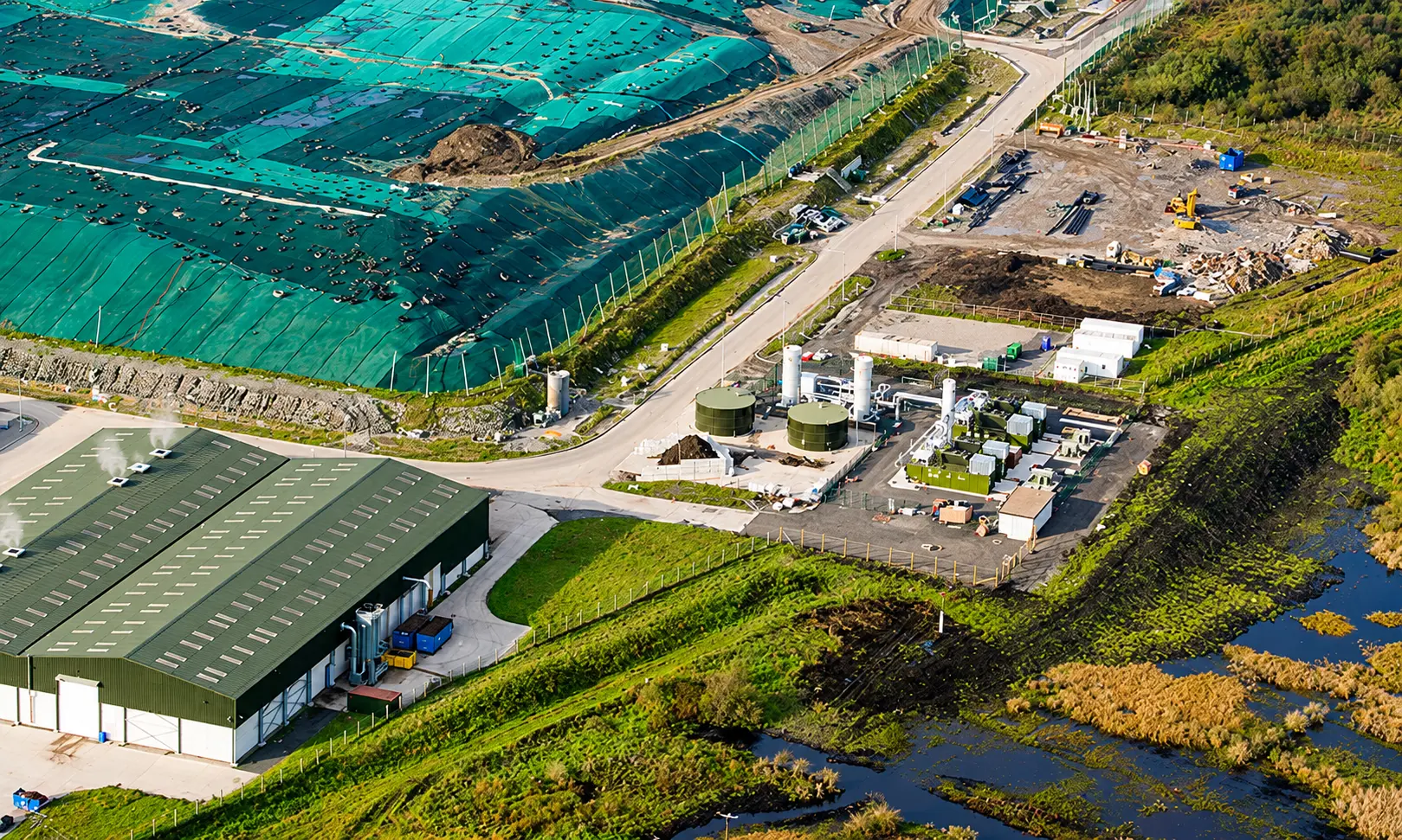
Landfills. The flare destroys collected landfill gas where it is not used for power, and stands by when the engines are down. Duty is long-term and continuous, flow and methane content change over the site’s life, and emission testing is routine. Turndown and low calorific value capability matter most.
Biogas plants. On agricultural, food waste and sewage treatment digesters, the flare burns surplus gas when the engine, boiler or upgrader is unavailable. Duty is intermittent, starts are automatic on high gas holder level, and the flare must be sized for the full gas production. Siloxanes are a concern on sewage gas.
Compressed biogas and biomethane plants. The flare takes the full raw gas flow when the upgrading unit trips, and product gas that is off specification during start-up or upsets. It is the safety disposal route for the whole plant, not only for surplus gas.
Landfill mining and dumpsite remediation. Excavating old waste releases trapped gas in surges, with falling methane content and rising oxygen. Trailer-mounted enclosed flares move with the working face (CRA: Mobile Enclosed Flares for Landfill Mining).
Pyrolysis and gasification. Start-up gas, off-specification syngas and gas released on upsets need safe disposal. Where the process also has a thermal oxidiser for continuous abatement, the enclosed flare is the disposal route when the oxidiser trips (CRA: TO and EGF engineered as one system).
Refining, chemicals and gas processing. Enclosed flares handle routine and moderate relief loads, tank vapours and vent streams at sites near communities, roads or other units, where a visible flame, glare or radiant heat at grade is not acceptable. Large emergency relief loads usually still go to an elevated or multi-point ground flare.
For a comparison of enclosed and open designs across these duties, see Enclosed vs Open Flares.
How to specify one: the data a manufacturer needs
A manufacturer can design an enclosed flare properly only from a complete picture of the gas and the duty. The data below is what the design depends on, with the reason each item matters.
If a figure is not known, a range with a note of the uncertainty is far more useful than a single guessed number. A flare designed for a composition that turns out to be wrong will either fail its temperature or be larger than it needed to be.
Common failure modes
Most enclosed flare problems in the field trace back to a handful of causes, and each has a design answer.
UK guidance calls for enclosed flares to be inspected every six months at both maximum and minimum rated capacity, and for emergency flares to be inspected at least annually so that they work when they are needed (LFTGN05). Regular test runs matter most for emergency flares, which can otherwise sit idle for months between calls.
Where CRA fits
CRA Energy designs and manufactures enclosed ground flares for landfill gas, biogas, biomethane and process gas duty, as fixed, skid-mounted and trailer-mounted units, together with the knock-out vessels, flame arresters, booster blowers and control systems that make up the flare train. Where a process also needs continuous abatement, CRA supplies the thermal oxidiser and the enclosed flare engineered as one system on a shared design basis.
To discuss a specific application, send the data in the table above to the CRA team.
References
1. Environment Agency, LFTGN05: Guidance for monitoring enclosed landfill gas flares, version 2, 2010.
2. Environment Agency and SEPA, Guidance on Landfill Gas Flaring, version 2.1.
3. UNFCCC Clean Development Mechanism, TOOL06: Project emissions from flaring, version 4.0.
4. UNFCCC Article 6.4 Mechanism, Draft methodological tool: Project emissions from flaring.
5. American Petroleum Institute, API Standard 537: Flare Details for Petroleum, Petrochemical, and Natural Gas Industries; table of contents.
6. ISO, ISO 25457:2023 Flare details for general refinery and petrochemical service.
7. US Code of Federal Regulations, 40 CFR Part 60 Subpart XXX: Municipal Solid Waste Landfills.
8. US Code of Federal Regulations, 40 CFR 264.1033: Closed-vent systems and control devices.
9. Umweltbundesamt, Biogasanlagen: TRAS 120 overview.
10. CRA Energy, Enclosed vs Open Flares: Which System Fits Your Application.
11. CRA Energy, A Thermal Oxidizer for Emissions, an Enclosed Ground Flare for Safety.
12. CRA Energy, Mobile Enclosed Flares for Landfill Mining and Dumpsite Remediation.